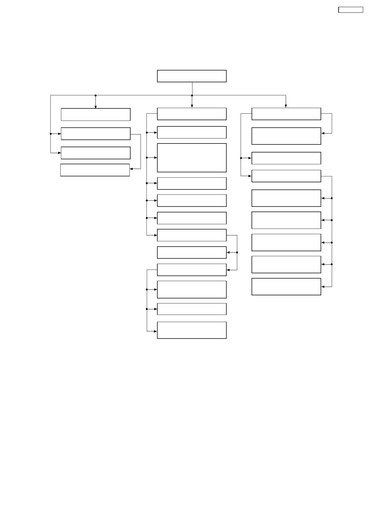
9.2. Disassembly flow chart
The following chart is the procedure for disassembling the casing and inside parts for internal inspection when carrying out the
servicing.
To assemble the unit, reverse the steps shown in the chart as below.
9.4. Top Cabinet
9.7 Front Panel 9.19 D-Amp P.C.B.
9.20 Audio Digital
Power Amp IC (IC5000)
9.23 Switch Regulator IC
(IC5701)
9.24 Switch Regulator Diode
(D5702)
9.25 Regulator Diode
(D5801)
9.26 Regulator Diode
(D5802)
9.27 Regulator Diode
(D5803)
9.21 Main P.C.B.
9.22 SMPS P.C.B.
9.12 CD Lid
9.10 USB P.C.B.
9.11 Music Port P.C.B.
9.9 Mic P.C.B.
9.13 Deck Mechanism Unit
9.17 Cassette Lid
9.14 Deck P.C.B.
9.16 Deck
Mechanism P.C.B.
9.15 Deck Mechanism
9.18 Rectification for Tape
Jam Problem
9.8 Panel, Tact Switch,
Remote Sensor P.C.B.
Side Bar (L) LED P.C.B.
Side Bar (R) LED P.C.B.
9.28 AC Inlet P.C.B.
9.29 DVD Module P.C.B.
9.5 Mechanism Unit (CR14)
9.6 Rear Panel
41
SA-VK470EE