Special Note: Ensure pins of the regulator diode (D5802) are
properly seated and soldered on SMPS P.C.B.
9.27. Replacement of Regulator
Diode (D5803)
•
• •
• Follow (Step 1) to (Step 3) of Item 9.3.
•
• •
• Follow (Step 1) to (Step 8) of Item 9.13.
•
• •
• Follow (Step 1) to (Step 6) of Item 9.19.
•
• •
• Follow (Step 1) to (Step 4) of Item 9.22.
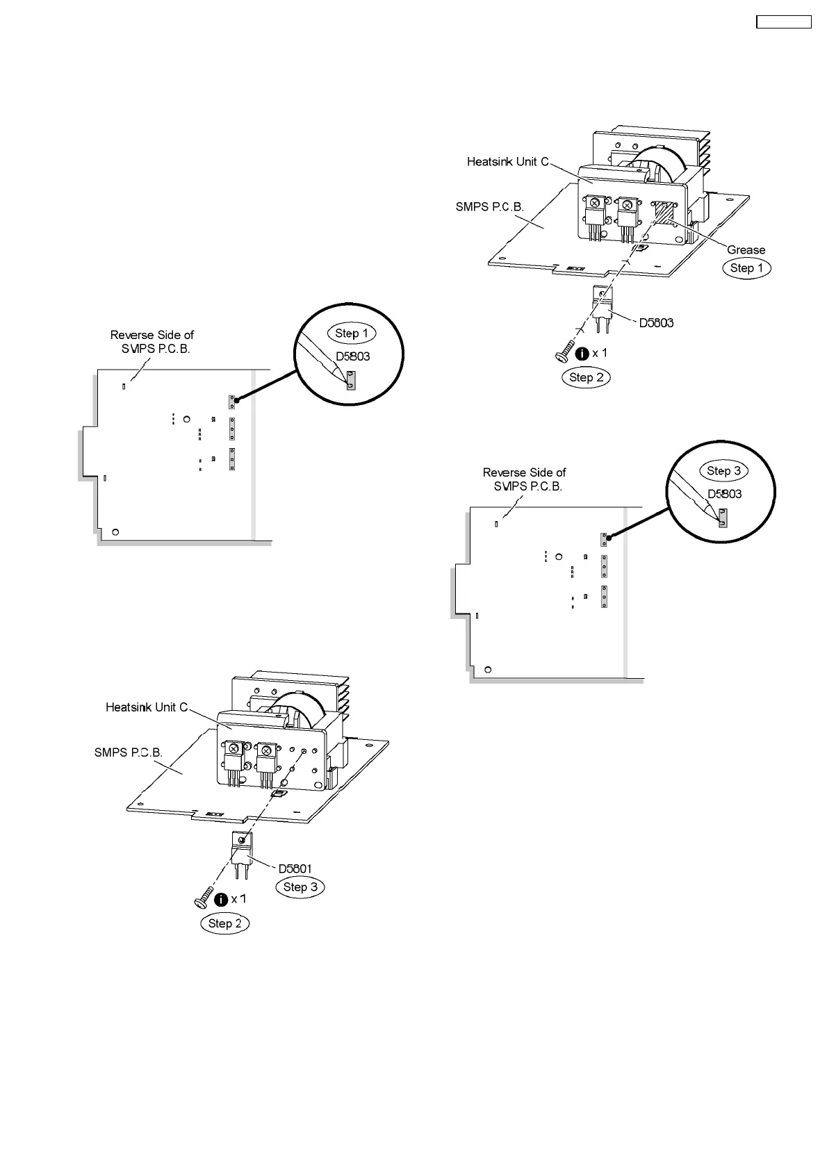
Step 1 Desolder pins of the regulator diode (D5803) on the
reverse side of SMPS P.C.B.
Step 2 Remove 1 screw from the regulator diode (D5803).
Step 3 Remove the regulator diode (D5803) from the heatsink
unit C.
Caution: Handle the heatsink unit C with caution due to its
high temperature after prolonged use. Touching it may
lead to injuries.
Note: Refer to the diagrams of SMPS P.C.B. (Item 20.5) for
location of the part.
9.27.1. Assembly of Regulator Diode
(D5803)
Step 1 Apply grease to the heatsink unit C.
Step 2 Fix and screw the regulator diode (D5803) to the
heatsink unit C.
Special Note: Ensure the regulator diode (D5803) is tightly
screwed to the heatsink unit C.
Step 3 Solder pins of the regulator diode (D5803) on the
reverse side of SMPS P.C.B.
Special Note: Ensure pins of the regulator diode (D5803) are
properly seated and soldered on SMPS P.C.B.
9.28. Disassembly of AC Inlet P.C.B.
•
• •
• Follow the (Step 1) to (Step 5) of Item 9.4
Step 1 Remove 2 screws at AC Inlet P.C.B..
Step 2 Cut 2 tie wraps.
65
SA-VK470EE