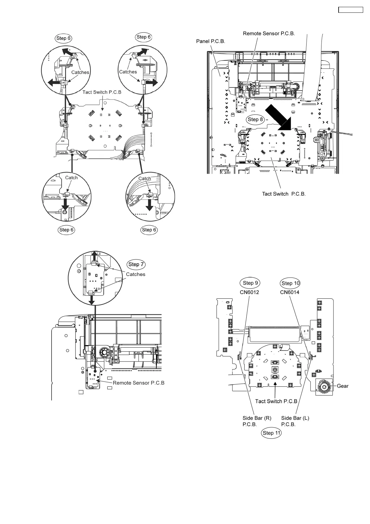
Step 7 Release 2 catches at Remote Sensor P.C.B..
Step 8 Lift up the Panel P.C.B., Tact Switch P.C.B. & Remote
Sensor P.C.B. altogether as arrow shown.
•
• •
• Disassembly of Side Bar (L) Led P.C.B. and Side Bar (R)
P.C.B.
Step 9 Detach Side Bar (L) P.C.B at the connector (CN6014)
on Panel P.C.B.
Step 10 Detach Side Bar (R) P.C.B at the connector (CN6012)
on Panel P.C.B.
Step 11 Remove the Side Bar (L) P.C.B. and Side Bar (R)
P.C.B.
Caution Notes:
1. During assembling of the P.C.Bs, ensure that the diode
shown on Tact Switch P.C.B. are in upright position.
49
SA-VK470EE
 Loading...