Chapter 1. Installation
11
PIN OUTS & SPECIFICATIONS — SERVO DRIVES ONLY
(15-pin “DRIVE” connectors)
Pin
* Name In/Out 71-017003-10
Cable Colors
***
Description
3 CMD + OUT Black
Command signal output to the drive.
±
10VDC analog output. 12-bit DAC. Load should be
>2k
Ω
impedance.
5 DFT IN Green Drive fault input. Set active level with the
DRFLVL
command (default is active low). The drive
fault input will not be recognized until you send a
DRFEN1
command (enables the input) to the
axis. Voltage range for the DFT input is 0-24V. Switching levels: Low
≤
1/3 VINref voltage,
High
≥
2/3 VINref voltage (factory default VINref voltage is +24VDC, but you can connect a
different voltage to the VINref terminal**). To make DFT a sinking input, connect the CNTRL-P
terminal** to the GND terminal**.
6 CMD – IN Red Command signal return.
7 SHTNO OUT Brown Shutdown relay output to drives that require an open contact to disable the drive. The
shutdown relay is active (disabling the drive) when no power is applied to the 6K. When the 6K
is powered up, the shutdown relay remains active until you issue the
DRIVE1
command to the
axis. Max. rating: 175VDC, 0.25A, 3W.
Shutdown active (
DRIVEØ
): this output is disconnected from COM.
Shutdown inactive (
DRIVE1
): this output is internally connected to COM.
(see schematic above)
8 SHTNC OUT Gray Shutdown relay output to drives that require a closed contact to disable the drive. The
shutdown relay is active (disabling the drive) when no power is applied to the 6K. When the 6K
is powered up, the shutdown relay remains active until you issue the
DRIVE1
command to the
axis. Max. rating: 175VDC, 0.25A, 3W.
Shutdown active (
DRIVEØ
): this output is internally connected to COM.
Shutdown inactive (
DRIVE1
): this output is disconnected from COM.
(see schematic above)
13 ISO GND ----- White Isolated logic ground.
14 COM ----- Yellow Signal common for shutdown. Not connected to any ground or other COM.
15 AGND ----- Blue Analog ground.
* Pin 1, 2, 4, and 9-12 are reserved for connection to a step & direction drive (see page 15).
** The VINref, CNTRL-P, and GND terminals are located on the screw-terminal connector on top of the 6K chassis.
*** The servo drive cable (p/n 71-017003-10) is a 10-foot cable with no connector on the drive end of the cable. It is sold as an accessory.
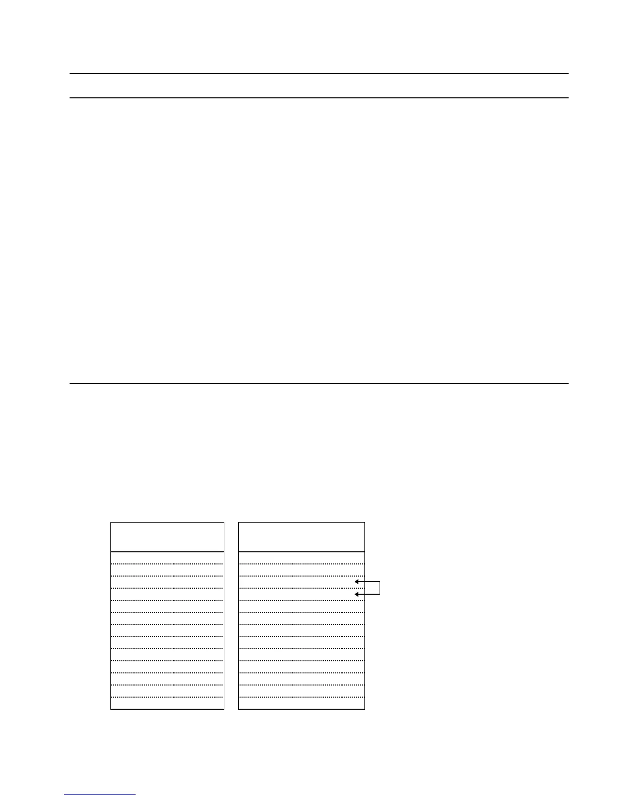
CONNECTIONS TO THE APEX SERIES DRIVE
APEX Drive Connections 6K Connections
Signal Name Signal Name Connector Pin
Enable In
↔
SHTNO DRIVE 07
Fault Out
↔
DFT DRIVE 05
Gnd
↔
AGND DRIVE 15
COM DRIVE 14
Command +
↔
CMD + DRIVE 03
Command –
↔
CMD – DRIVE 06
CHA +
↔
A + ENCODER 02
CHA –
↔
A – ENCODER 03
CHB +
↔
B + ENCODER 04
CHB –
↔
B – ENCODER 05
CHZ +
↔
Z + ENCODER 06
CHZ –
↔
Z – ENCODER 07
Gnd
↔
GND ENCODER 09
Jumper AGND to COM.
 Loading...