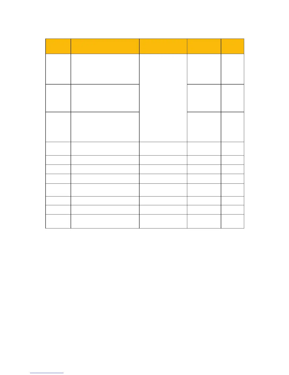
EasyManuals Logo

Parker AC10 series Quick Start Guide

Parker AC10 series
60 pages
To Next Page IconTo Next Page
To Previous Page IconTo Previous Page
Page #46 background imageLoading...
Page #46 background image
Function
Code
Function Denition Setting Range
Mfr’s Value Change
F300 Relay output
0: No function
1: Inverter fault
4: Free stop
(coast stop)
5: In running
status 1
15: At speed
Refer to Product
manual for
additional
settings
1
F301 DO1 output 14
F302 DO2 output 5
F303-
F306
Reserved
F307 Target frequency 1 F112-F111 10.00
F308 Target frequency 2 F112-F111 50.00
F309 Target frequency width (%) 0-100 50
F310 Target current (A) 0-1000
Rated
current
F311 Target current width (%) 0-100 10
F312 At speed threshold (Hz) 0.00-5.00 0.00
F313-
F315
Reserved
10-7 Parameter List and Default Settings

Other manuals for Parker AC10 series

Questions and Answers:

Question and Answer IconNeed help?

Do you have a question about the Parker AC10 series and is the answer not in the manual?

Parker AC10 series Specifications

General IconGeneral
Overload Capacity150% for 60 seconds
Analog Inputs2
Analog Outputs1
Communication OptionsModbus RTU
Protection RatingIP20
Input Voltage200-240VAC, 380-480VAC, 500-575VAC, 600VAC, 690VAC
Digital Outputs2
ProtectionOvercurrent, Overvoltage, Undervoltage, Overtemperature, Short Circuit
Operating Temperature-10°C to +50°C
Humidity5% to 95% (non-condensing)
DimensionsVaries by model
WeightVaries by model
BrakingBuilt-in dynamic braking

Related product manuals