EasyManuals Logo

Parker AC20 Series User Manual

Parker AC20 Series
154 pages
To Next Page IconTo Next Page
To Previous Page IconTo Previous Page
Page #105 background imageLoading...
Page #105 background image
DOC-0017-04-EN: AC20 Series - Hardware Installation Manual
DOC-0017-04-EN-A 22.03.2023 105 (154)
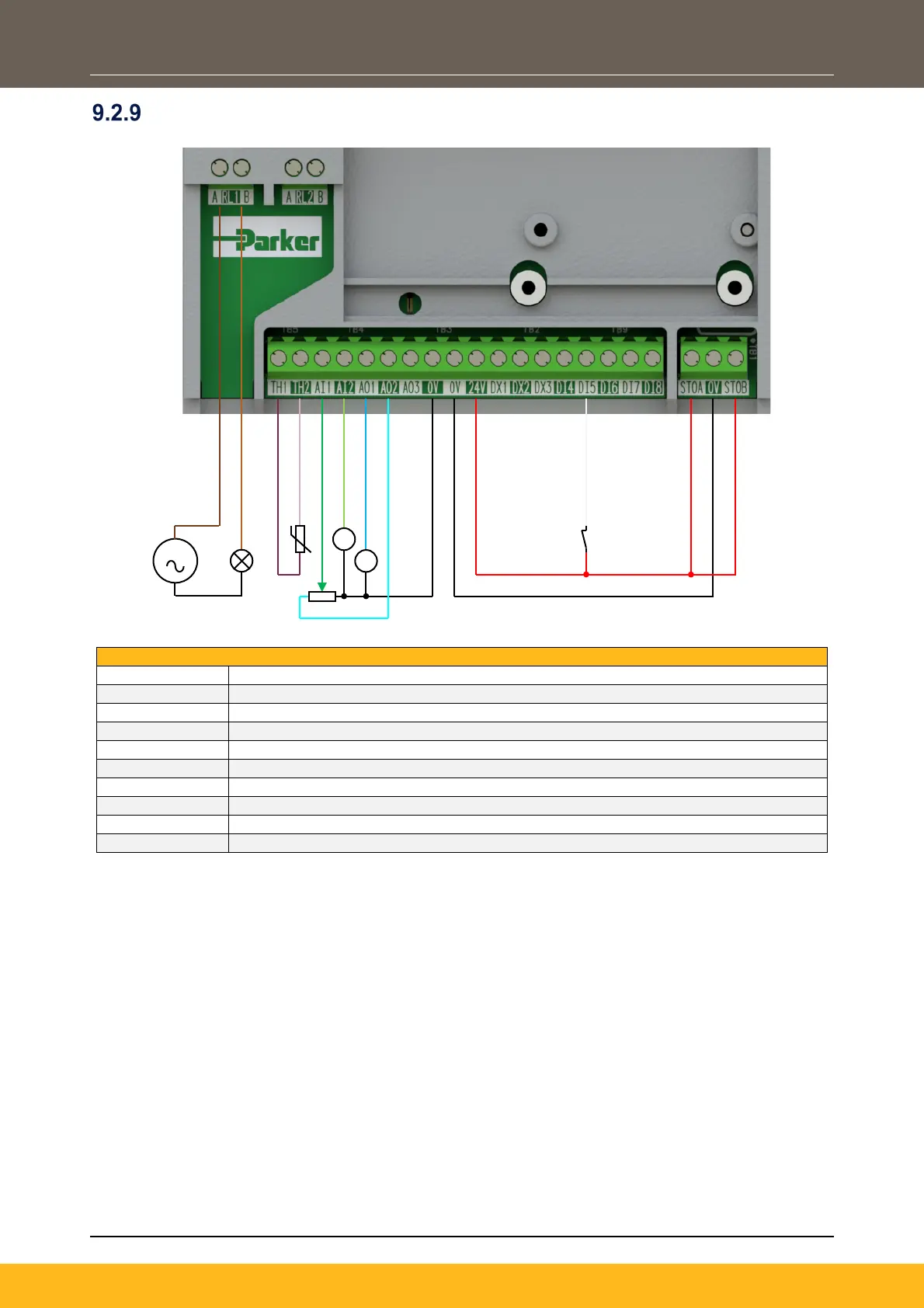
Application ‘6’: Aux Comms
Configuration Setup:
RL1A
110-230Vac (or 24Vdc) voltage supply
RL1B
Healthy: Relay output (to lamp)
TH1
Motor Thermistor ‘+’ connection
TH2
Motor Thermistor ‘-connection
AI1
Remote Setpoint (%) input 1: 0-10V variable input (from potentiometer)
AI2
Remote Setpoint ‘Trim’ (%) input 2: 4-20mA variable input (from current source)
AO1
Speed Demand (%): 0-10V variable output (to voltmeter)
AO2
Value = 100%: 0-10V variable output (+10V fixed reference voltage)
DI5
Not Coast Stop: 24V digital input
STO
STO DISABLED (drive operational)
V
V
S

Table of Contents

Other manuals for Parker AC20 Series

Questions and Answers:

Question and Answer IconNeed help?

Do you have a question about the Parker AC20 Series and is the answer not in the manual?

Parker AC20 Series Specifications

General IconGeneral
BrandParker
ModelAC20 Series
CategoryConference System
LanguageEnglish

Related product manuals