DOC-0017-04-EN: AC20 Series - Hardware Installation Manual
DOC-0017-04-EN-A 22.03.2023 143 (154)
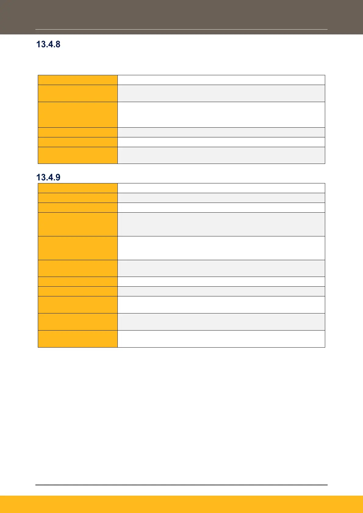
External +24V Auxiliary Input
Allows for the partial power-up of the product without mains power applied, for programming of the drive
using the DSELite programming tool through the Ethernet port, or communication with the drive through the
Anybus Comms option. µSD Card port, display, keypads and digital I/O are also active.
Input Voltage:
24V +/-10% (up to a maximum ambient temperature of 40°C)
24V +5 / -10% (up to a maximum ambient temperature of 45°C)
Indicative Input Current:
- Control Board only: 45mA
- Control Board with EtherCAT comms option fitted only: 85mA
Reverse Voltage
Protection:
No
STO Inputs
STOA, STOB, referenced to 0V
24V PELV (with energy source class 3, according to IEC 62368-1)
Maximum Input Voltage:
25.2V (26.4V in a maximum operating ambient of 40°C)
Recommended Input
Voltage for Logic Low
Level:
0V – 5V (or open circuit)
Recommended Input
Voltage for Logic High
Level:
15V – 24V
Indetermined Input
5V – 15V, function is undefined
Always Active (i.e., STO cannot be disabled by the drive firmware)
STO User Input A Logic
0V or open circuit = STO Activated
24V = STO Disabled
STO User Input B Logic
Level:
0V or open circuit = STO Activated
24V = STO Disabled
Isolation:
Channel A & B to SELV: Galvanic Isolation.
Channel A to Channel B: Non-isolated
 Loading...