EasyManuals Logo

Parker AC20 Series User Manual

Parker AC20 Series
154 pages
To Next Page IconTo Next Page
To Previous Page IconTo Previous Page
Page #106 background imageLoading...
Page #106 background image
DOC-0017-04-EN: AC20 Series - Hardware Installation Manual
106 (154) DOC-0017-04-EN-A 22.03.2023
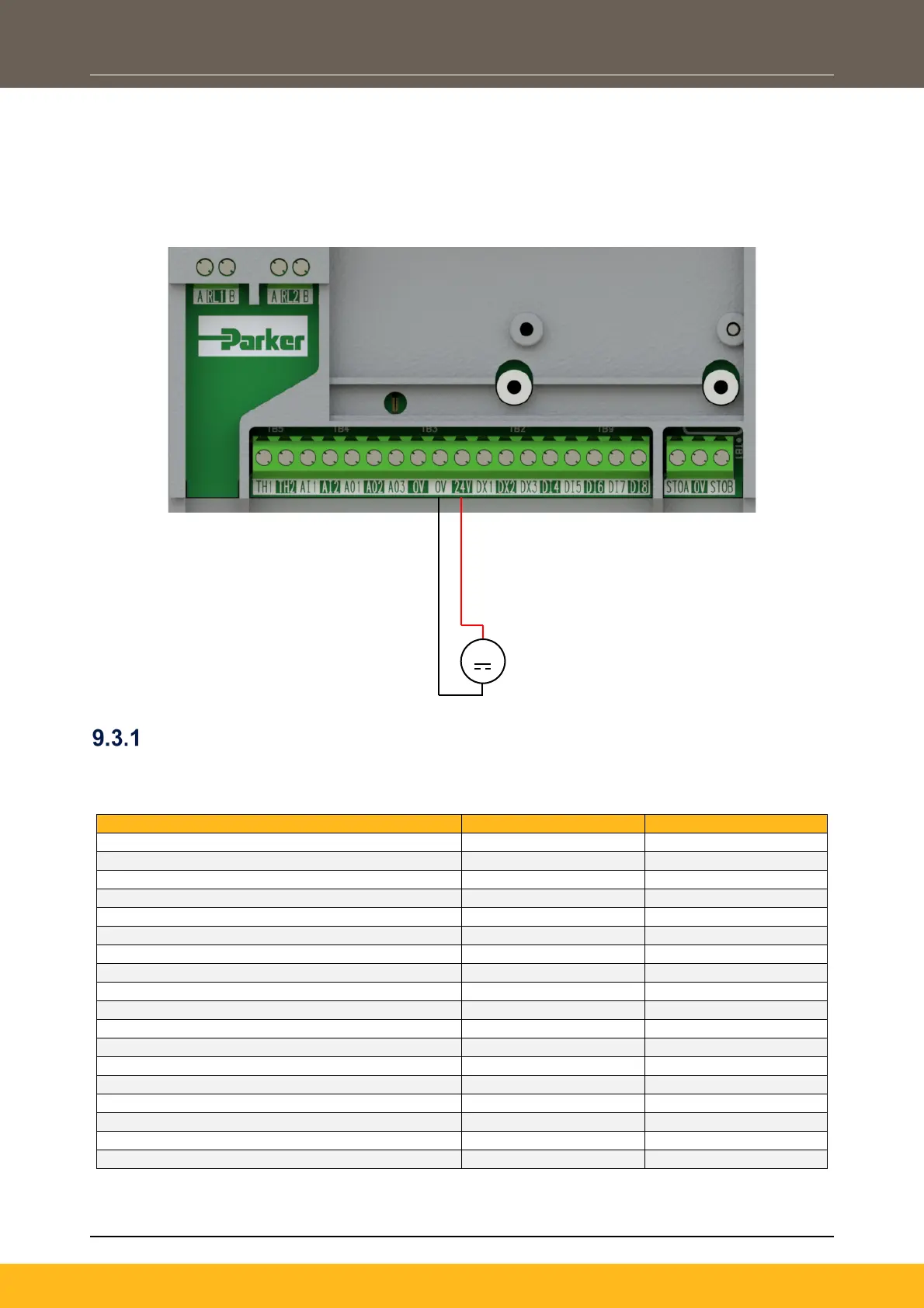
9.3 External +24V Power-Up Mode
Allows for the partial power-up of the product without mains power applied, for programming of the drive
using the DSELite programming tool through the Ethernet port, or communication with the drive through the
Anybus Comms option. µSD Card port, display, keypads and digital I/O are also active.
The external power supply is connected as per the diagram below:
24V Active Functionality
Although in 24V power-up mode the drive cannot run a motor, a limited number of circuits and functions are
still active, as summarised in the table below:
Product Function
Frame 2 - 5
Frame 6 - 10
On-board Display
On-board Keypad
Status LEDs
P3 Port (6901 Remote Keypad)
Ethernet Port
µSD Card Slot
Analogue Inputs
x
x
Analogue Outputs
x
x
Digital Inputs
Digital Outputs
Relay Outputs
x
x
Motor Thermistor
x
x
STO
x
x
PWM Outputs
x
x
Power Stack Feedbacks
x
x
Encoder Feedback Option Card
x
x
GPIO Option Card
x
x
Anybus Comms Options
+24V

Table of Contents

Other manuals for Parker AC20 Series

Questions and Answers:

Question and Answer IconNeed help?

Do you have a question about the Parker AC20 Series and is the answer not in the manual?

Parker AC20 Series Specifications

General IconGeneral
BrandParker
ModelAC20 Series
CategoryConference System
LanguageEnglish

Related product manuals