DOC-0017-04-EN: AC20 Series - Hardware Installation Manual
DOC-0017-04-EN-A 22.03.2023 139 (154)
Power Supply = 3ø 380-480V ±10%, 50/60Hz ±10%, PSCC = 5kA
Motor power, output current and input current must not be exceeded under steady state operating
conditions.
Minimum repetitive power up / power down cycle time = 10 mins.
Frame
Motor
Power
Output
Current
Input
Current
Est. Eff
Switching
Frequency
(kHz)
AC
Current
Derate
8
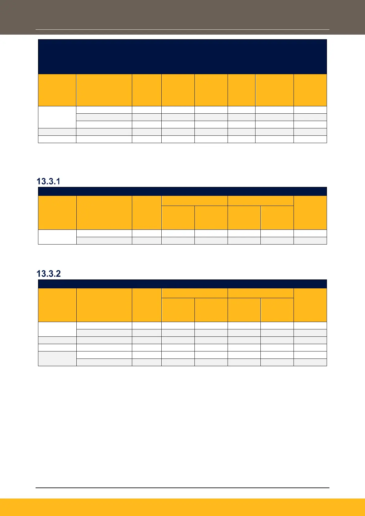
13.3 Internal Brake Switch Ratings
1ø, 230V Products
DC Link Brake Switch Threshold = 382V
Frame
Size Product Code
Motor
Power
(kW)
Continuous Peak (Instant)
Min
Resistor
Value
(Ω)
Brake
Current
(A)
Power
Diss
(kW)
Brake
Current
(A)
Power
Diss
(kW)
2
Note: Peak (Instant) = Maximum 20sec, 30% ‘on’ duty (except where this value is the same as the
continuous rating)
3ø, 230V Products
DC Link Brake Switch Threshold = 382V
Frame
Motor
Power
Min
Resistor
Value
Brake
Current
Power
Diss
Brake
Current
Power
Diss
2
5
Note: Peak (Instant) = Maximum 20sec, 30% ‘on’ duty (except where this value is the same as the
continuous rating)
 Loading...