DOC-0017-04-EN: AC20 Series - Hardware Installation Manual
DOC-0017-04-EN-A 22.03.2023 37 (154)
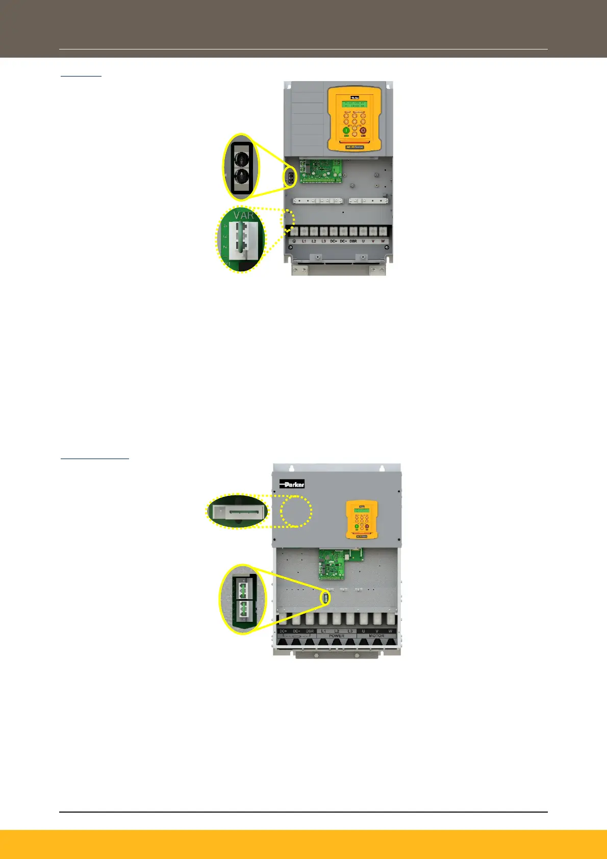
Frame 6:
To access the Y-Cap links:
1. Remove the Lower Terminal cover.
2. Remove the 2x screws from the product.
To access the VDR link, it is necessary to open the product:
1. Remove the Lower Terminal cover.
2. Carefully remove the Upper Terminal cover, disconnecting the onboard keypad cable from the top
of the control board.
3. Remove the 4x plastic moulding fixings screws from the four corners of the product.
4. Carefully lift the power stack cover with the control board attached - just enough to adjust the link
position.
Note: All power cables must be removed from the product to access this link.
Frames 7 – 10:
To access the AC Line Y-Cap & VDR links:
1. Remove the Lower Terminal cover.
2. Adjust the link positions. Removing the link completely is the same as placing the links in the
‘disconnected’ (pin 2 – 4) position.
To access the DC Link Y-Cap link:
1. Remove the Lower Terminal cover.
2. Carefully remove the Upper Terminal cover, disconnecting the onboard keypad cable from the top
of the control board.
3. Adjust the link position of CN5. Removing the link completely is the same as placing the link in the
‘disconnected’ (pin 2 – 4) position.
AC Line Y-Cap
Screws (x2)
Y1 ’VAR’
VDR Li
nk
J1 ‘EMC’ AC
Line Y-C
ap &
Y1 ’VAR’
VDR Links
CN5 DC Link
Y
-Cap Link
 Loading...