DOC-0017-04-EN: AC20 Series - Hardware Installation Manual
76 (154) DOC-0017-04-EN-A 22.03.2023
3. Close the ‘Drive Start PB’ switch to run the drive.
To stop the drive:
1. Open the ‘Drive Stop PB’ switch and wait for the motor to come to a standstill.
To invoke STO:
1. Open the ‘Safety Demand’ contacts.
2. If the motor is running, the Safety Control Unit output Q1 will initiate a drive ‘Stop’ to decelerate the
motor to a standstill.
3. Safety Control Unit outputs Q3 & Q4 are configurable DODE (Delay on de-energise) signals that
will de-energise on initiation, after a delay time.
The delay time must be setup on the Safety Control Unit device so that the maximum deceleration
time of the drive has ensured the motor is at a standstill before the delay time has elapsed.
Note: Opening the ‘STO Demand’ contacts when the motor is running with an insufficient
delay time set, will result in the motor coasting to a stop.
4. Once the time delay has elapsed on Safety Control Unit outputs Q3 & Q4, the outputs will de-
energise, and hence STO will now be ‘Active’ on the drive for as long as required.
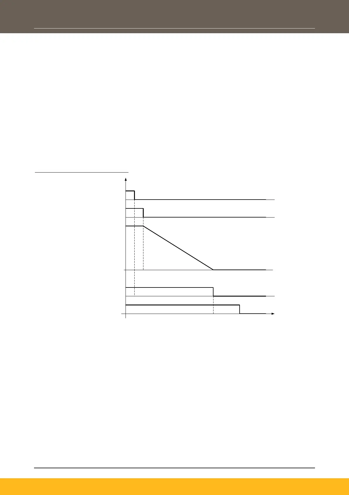
Timing diagram (Typical Operation):
Stop
Speed
Emergency Stop
Drive STO input, Ch A & B
No torque at motor shaft
Torque at motor shaft active
Configured deceleration time in drive
Configured delay time in UE410-MU
STO delay time
inside drive
< 15 ms
t
Note: The Q1 output signal from the Safety Control Unit works using test pulses. Therefore, the
digital input signal received by the drive must filtered. This can be implemented by adding a
‘Debouncing’ Function block to the relevant input signal using the DSELite configuration tool.
In the example illustrated, the contacts of the ‘Safety Demand’ (i.e., Emergency Stop button) need to be
designed mechanically linked, in accordance with EN 60947-5-1, annex K.
Other Safety Control Units can be used if it meets all requirements for cat 3 and PLd that have a high-
quality fault detection method with dynamic cross monitoring test pulses. The maximum test pulse time of
these devices must be < 1.5msec (active low OSSD).
For the delayed initiation of STO, the machinery risks have to be considered from the machine designer.
 Loading...