Parker Hannifin S.p.A. - S.B.C. Division HPD N User’s Manual
21
In the first case the scheme to use is the follow:
7
1
0V
2
3
4
X6
8
6
5
9
HPD
A
A
B
B
In case of parallel connections to more than one HPD,
connections to pins 9, 5, 6, and 8, must
be made only on the last drive in the group.
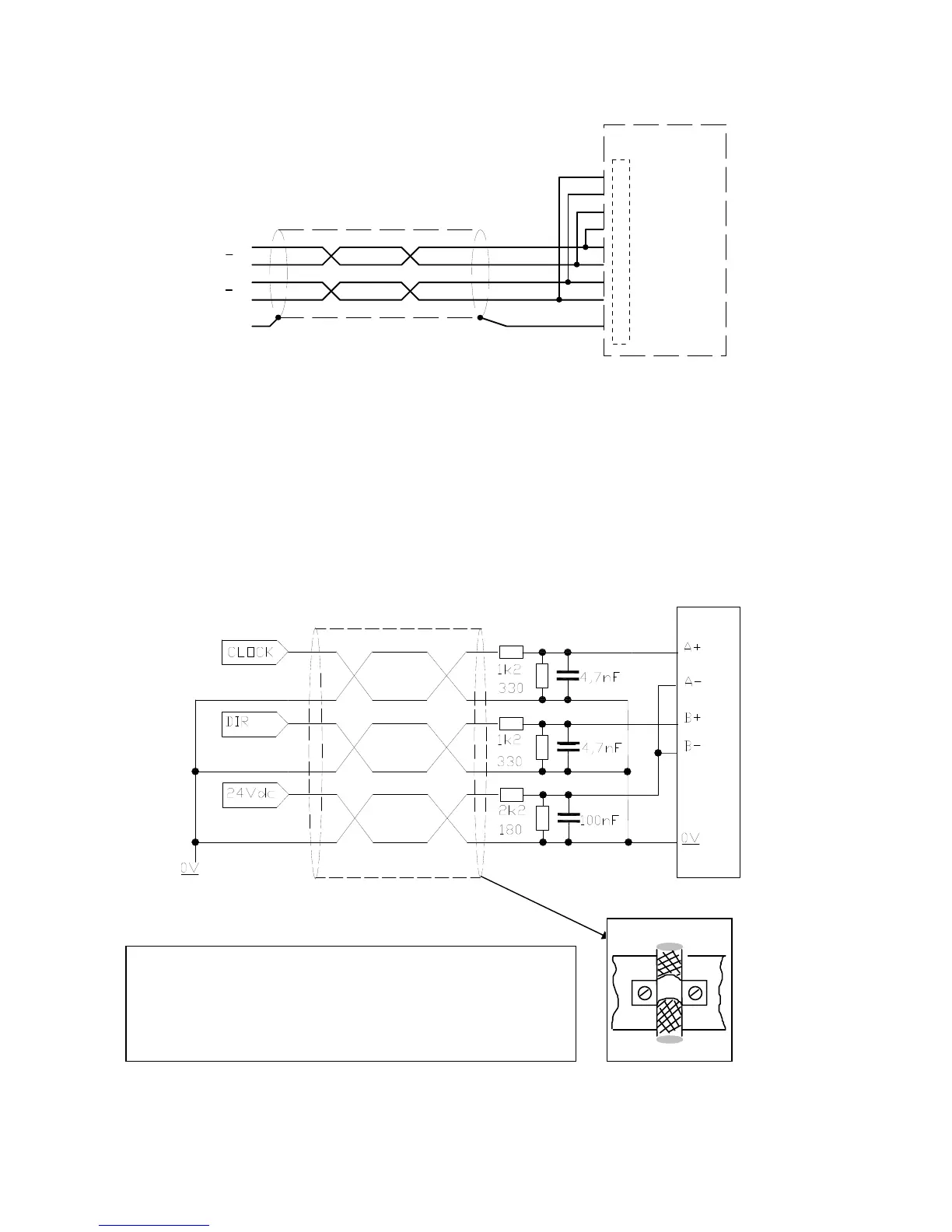
In the second case, there are two possible solution for to control the drive with input signal
from X6 frequency/direction type:
-
by “PLC-Line driver interface” board (available to our products);
-
by showed below.
When CLOCK and DIR signals are to 24Vdc, execute the connections: channel A is dedicated
to frequency while channel B to direction.
O
O
O
- Cable shielded with 3twisted pairs.
- Connect the resistances near to the terminal of the drive
(max. 5cm).
- For the fixing of the cable-shields use the connections
shown on the picture beneath.
360° connection