Parker Hannifin S.p.A. - S.B.C. Division HPD N User’s Manual
22
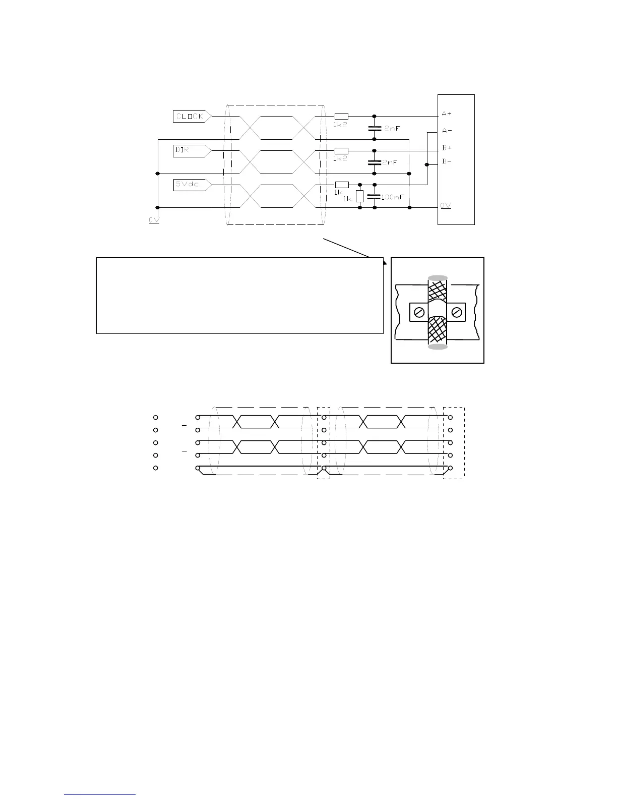
When CLOCK and DIR signals are to 5Vdc, execute the connections:
HPD connection with digital locking
1
2
3
4
7
X6 (HPD)
X6 (HPD)maste
A
A
B
B
GND
1
2
3
4
7
X7 (HPD)
see text for burden resistors
The example in the figure shows the connection between two HPD drives in digital lock
with a master, but this configuration can be extended to several drives connected in series. On
the final drive in the series connect the burden resistors by jumpering pin 1 with pin 9, pin 2
with pin 5, pin 3 with pin 6 and pin 4 with pin 8 on connector X6. The master can be an
externally fed encoder, or the simulated encoder output on another drive.
The signal from the master encoder must be differential type 5V RS-422; it is therefore
possible to connect a maximum of 10 slave HPDs.
If the master is an HPD drive, then up to 32 units can be connected in digital lock mode
using the same simulated encoder signal (RS-422 standard).
For the relative programming of the HPD, consult the
Digital locking chapter in this
manual.
360° connection
- Cable shielded with 3twisted pairs.
- Connect the resistances near to the terminal of the drive
(max. 5cm).
- For the fixing of the cable-shields use the connections
shown on the picture beneath.