6. Adjust the module position with the other thumb-wheels so that the module is parallel to the fas-
tening plate (step E).
7. Screw the 2 screws to lock the module position on the fastening plate (screws on the fastening
plate) (step F).
8. Tighten the 4 nuts with a spanner (step G).
–
apply a torque of 6 N·m.
Depending on configuration, the electronic drive unit can be installed laterally to the pump.
5.2 Positioning the equipped pump on the installation
The turbomolecular pump fastening must be connected and secured. To ensure personnel
safety and the reliability of operation (see chapter Installation of the pump operating in-
structions).
►
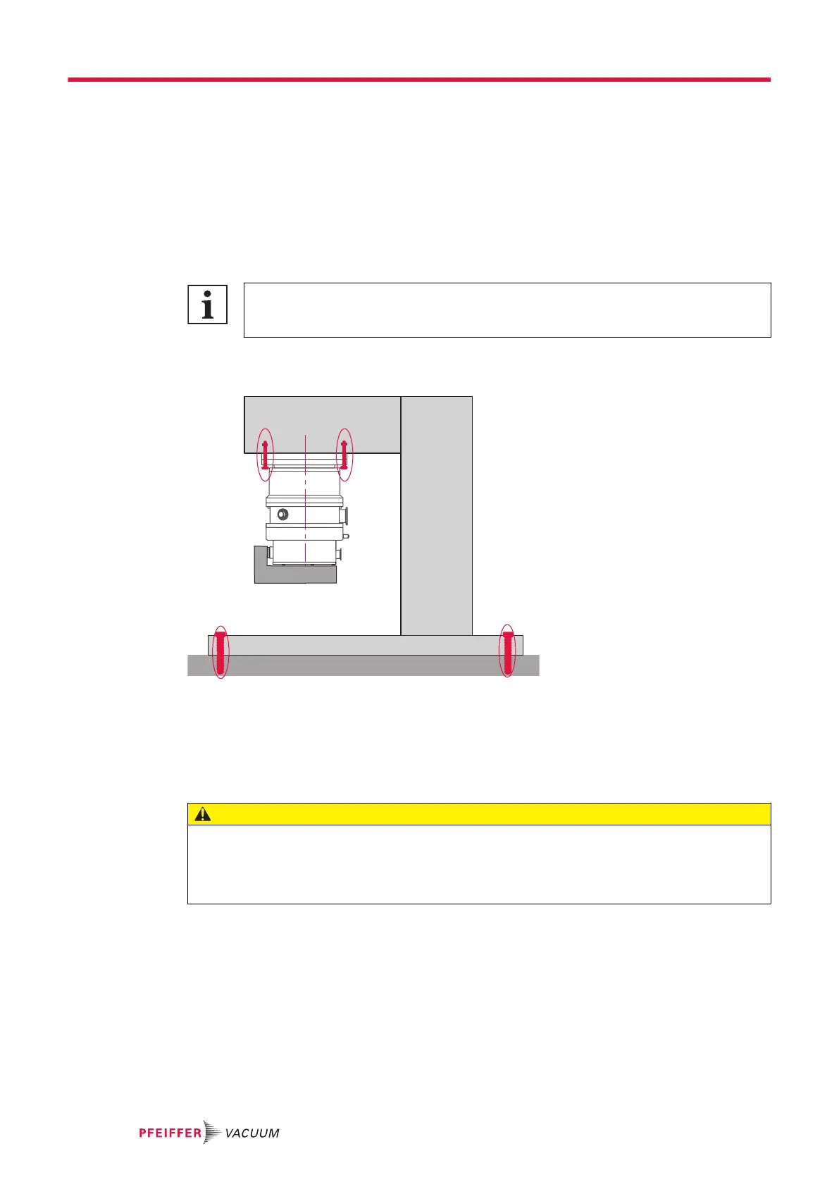
Use the lifting devices to position the pump in the desired location, lift the pump using lifting rings
(see chapter “Transport” of the pump operating instructions).
1 Vacuum chamber 4 ATH M/MT turbomolecular pump
2 Equipment 5 Electronic drive unit (OBC)
3 Frame
Installation of the inlet pump in horizontal position
►
To position the pump with a horizontal pumping axis, use a strap.
CAUTION
Risk of falling due to poorly-secured cables or pipework
The space around the pump must be kept clear of obstacles to prevent falls from potentially occur-
ring.
►
Route and secure electric cables and pipework in the appropriate pathways.
5.3 Connecting the water circuit
To limit corrosion and clogging of the water circuit, we recommend using softened or non-aggres-
sive water with the required characteristics (see chapter "Water characteristics"). If the solid pollution
characteristics cannot be met, install a filter on the water inlet.
Installation
18/60
 Loading...