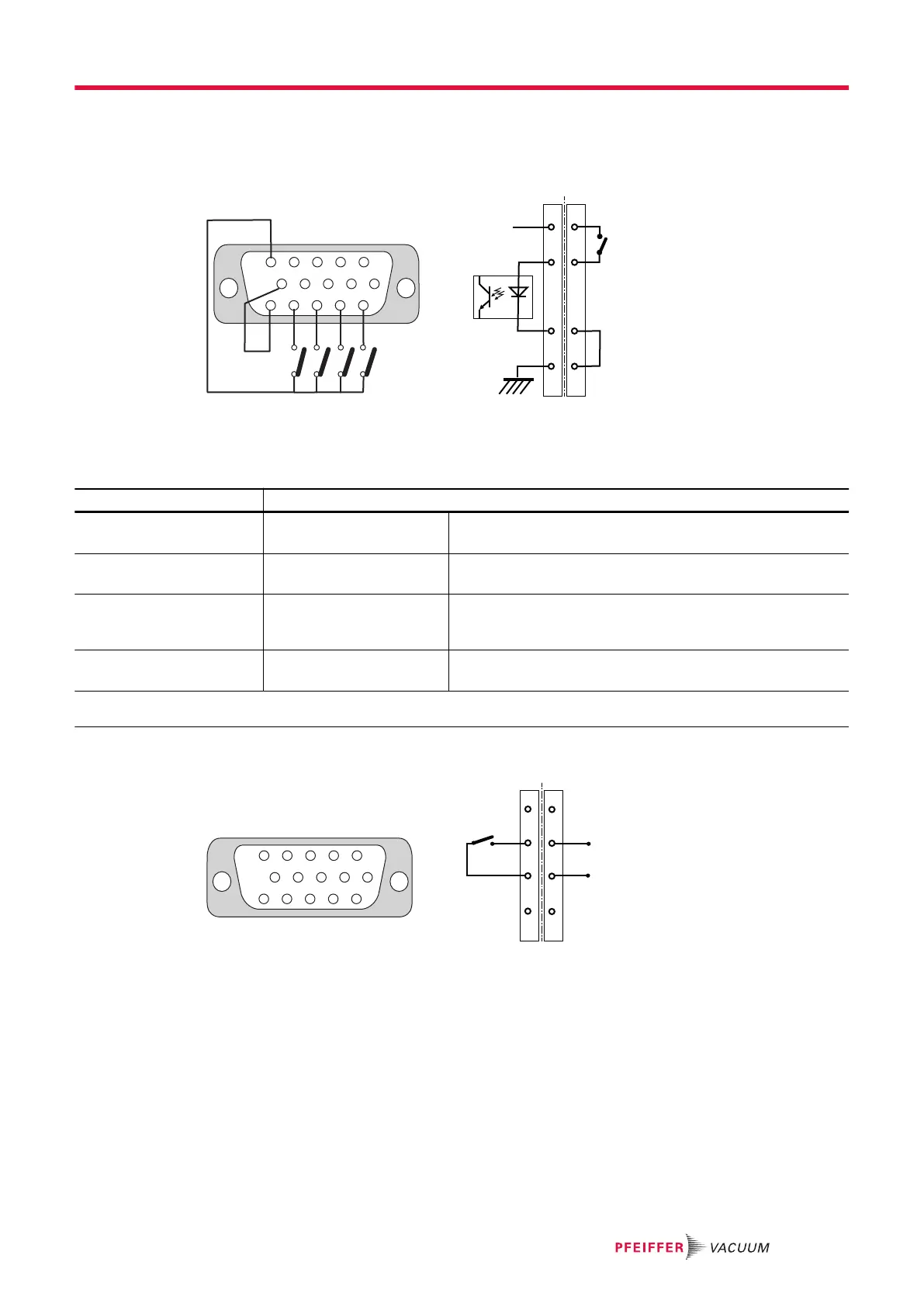
Control by dry contacts
To control these inputs by external contacts of the host equipment, connect pins 10 with 15 and wire the
used contacts (wiring customer supplied). Pins 11, 12, 13, 14 are connected to + 15 V (pin 5) to be ac-
tive.
5 4 3 2
1
6
1115
10 9 8
7
S4 S3 S2 S1
A B
S
11, 12, 13, 14
+15 V
GND
5
(+)
15
10
(-)
15
5
(+)
(-)
10
Fig. 7: Remote connector: control by dry contacts
A Internal wiring B Wiring from customer's side
Contact Function
S1 (11-5)
Purge
1)
Contact closed: the purge solenoid valve is activated.
Contact open: the purge solenoid valve is not activated.
S2 (12-5)
Venting
1)
Contact closed: the air inlet solenoid valve is activated.
Contact open: the air inlet solenoid valve is not activated.
S3 (13-5)
Stand-by
1)
Contact closed: Stand-by speed is selected.
Contact open: pump rotation speed is the pump nominal
speed.
S4 (14-5)
Start/Stop pump
1)
Contact closed: the pump starts.
Contact open: the pump stops.
1) This function runs when the control mode is set to ‘Remote hard’ via the RS-232/RS-485 serial link (see chapter “List of
commands”) or via HHR (see chapter “SETUP menu”).
8.3.2 Logic output wiring
5 4 3 2
1
6
1115
10 9 8
7
A B
4, 3, 2, 1
9, 8, 7, 6
Fig. 8: Remote connector: logic outputs
A Internal wiring B Wiring from customer's side
Interfaces for control
35/60
 Loading...