When a power failure occurs, the rotor remains suspended by the energy emitted by the motor’s coun-
ter-electromotive force, until the rotor rotation speed is low enough that it can rest on the landing bear-
ings without being damaged.
If the power is restored before the minimum speed is reached, the pump recovers its initial speed with-
out any disturbance. The landing bearing counter does not decrease.
Otherwise, if the minimum speed is reached before the power supply has been restored:
●
The pump lands on its landing bearings.
●
The electronic drive unit is powered off; no indicator light is on.
●
The landing bearings’ counter decreases.
Start up the pump according to the standard start-up procedure when the mains supply has been re-
stored.
6.3.2 Powering off
1. Power off the pump by setting the main switch to O:
–
the green LED turns off;
–
wait for the rotor to completely stop rotating.
2. Turn on the customer’s electrical installation breaker.
6.3.3 Prolonged stoppage
If the pump has to be stopped for a prolonged period, follow the shutting down procedure (see chapter
"Decommissioning").
6.4 Operation monitoring
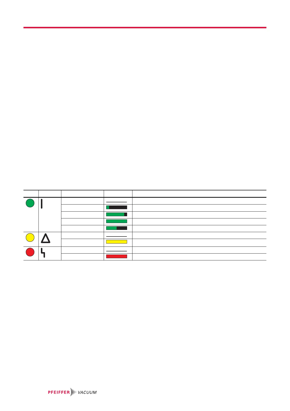
LED Symbol LED status Display Meaning
off Switched off.
on, flashing 10 %
Power supplied. Pump stopped or rotation speed < 60 min
-1
.
on, flashing 90 % The pump has not reached the selected speed.
on, constant light The pump has reached the selected speed.
on, flashing 50 %
The pump speed decreases, speed > 60 min
-1
.
off No warning
on, constant light Electronic drive unit initialized or warning signaled.
off No fault.
on, constant light Pump is faulty.
Tbl. 1: Meaning of LED on the control panel
When a problem occurs, the user is warned by:
●
Activation of the fault/warning LED
●
Audible warning of the HHR (if enabled)
●
Activation of the fault contacts on the Remote connector
●
Pumping interruption when the ‘Stop’ order has not been activated
●
Fault/warning message displayed on the HHR
●
A message via the RS-232 or RS-485 serial link
●
A message via the fieldbus
Fault messages are listed in the instructions; see chapter “Malfunctions”.
Operation
28/60
 Loading...