8.3 Control via the REMOTE connector
NOTICE
Safety of Extra-Low Voltage circuits
Remote control circuits are equipped with dry contact outputs (24 V - 1 A max). Overvoltages and
overcurrents can result in internal electrical damage. Users must observe the following wiring condi-
tions:
►
Connect these outputs in accordance with the rules and protection of Safety Extra-Low Voltage
(SELV) circuits.
►
The voltage applied to these contacts should be less than 24 VDC and the current less than 1 A.
Description
Connection via the REMOTE connector (HD, 15-pin D-Sub female) can be used for:
●
remote control of following functions: start, stop, purge, and air inlet
●
remote pump status through auxiliary dry contacts
The remote control mode is active when the ‘Remote hardware’ control mode is set on the RS-232/
RS-485 serial link or via the HHR unit.
When the ‘Remote hardware’ control mode is set, the Stand-by speed and temperature setpoint can be
set via the RS-232/RS-485 serial link or the HHR unit.
►
Use shielded cable and connect both sides to the ground.
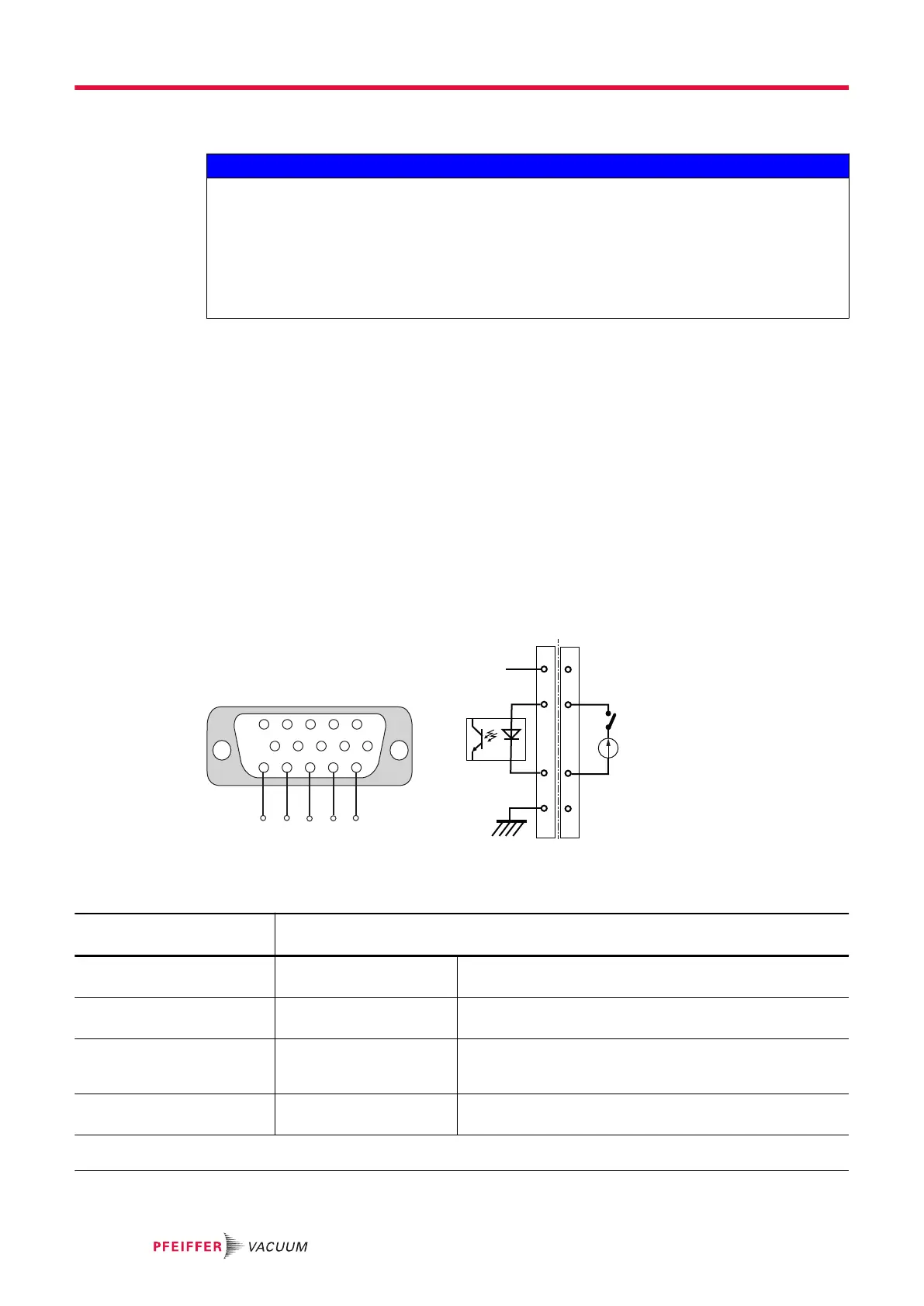
8.3.1 Logic input wiring
Control by direct voltage
The inputs are active when a DC voltage between 10 and 24 VDC is applied between their pins (wiring
customer supplied).
5 4 3 2
1
6
1115
10 9 8
7
+-
+
+
+
10-24 VDC
S
5
(+)
(-)
15
10
5
(+)
(-)
GND
15
10
11, 12, 13, 14
A B
+15 V
Fig. 6: Remote connector: control by direct voltage
A Internal wiring B Wiring from customer's side
Voltage
10-24 VDC
Function
S1 (11-15)
Purge
1)
Contact closed: the purge solenoid valve is activated.
Contact open: the purge solenoid valve is not activated.
S2 (12-15)
Venting
1)
Contact closed: the air inlet solenoid valve is activated.
Contact open: the air inlet solenoid valve is not activated.
S3 (13-15)
Stand-by
1)
Contact closed: Stand-by speed is selected.
Contact open: pump rotation speed is the pump nominal
speed.
S4 (14-15)
Start/Stop pump
1)
Contact closed: the pump starts.
Contact open: the pump stops.
1) This function runs when the control mode is set to ‘Remote hard’ via the RS-232/RS-485 serial link (see chapter “List of
commands”) or via HHR (see chapter “SETUP menu”).
Interfaces for control
34/60
 Loading...