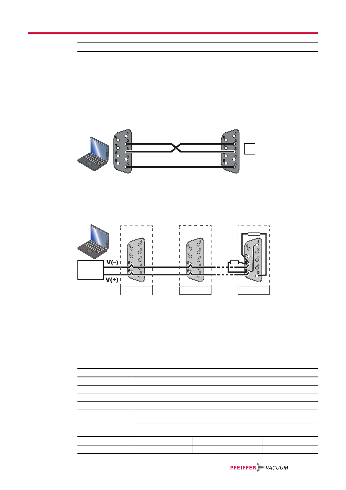
Pin Assignment
2 Data reception (RS-232)
3 Data transmission (RS-232)
5 GND
8 RS-485: V-
9 RS-485: V+
The user must use shielded links and connections in compliance with EMC and electrical safety stand-
ards.
RS-232 connection
A computer manages a single pump (P1) using the RS-232 link via the RS-232/RS-485 connector.
RS-485 connection
A computer manages several pumps (P1, P2, Pn, etc.) using a RS-485 serial link via the RS-232/
RS-485 connector. This parallel wiring allows communication between the pumps even if a pump is dis-
connected.
The wiring of the product at the end of line Pn* and the wiring of a single product on the network is spe-
cific.
RS-485
communication
box
P1 P2
Pn*
1,5 kΩ / 1/4 W
120 Ω / 1/4 W
Setting
The serial link control mode is active when the wiring is done and when the ‘Serial link’ control mode is
configured by the HHR (see chapter “SETUP” menu) or on the RS-232/RS-485 serial link (see chapter
“Command list”).
►
Position the mains switch to I.
►
Send an order via the serial link.
8.4.2 Communication protocol
Control commands
Header character The default setting is the decimal code 035 of the character #
Address Number given to the pump, 3 characters
Ordre Command sent on serial link, 3 characters
Order The number of characters depends on the command
Parameter This is the message end character. The setting is ASCII 13 code <CR> The
<LF> character is not taken into account.
Example:
Header character Pump address Order Order Parameter End character
# ADR ODR XXXX <CR>
Interfaces for control
37/60
 Loading...