6 Operation
6.1 Preliminary precautions for use
WARNING
Risk of electric shock in the event of electrical disconnection while the pump is running
The turbomolecular pump and its electronic drive unit cannot be disconnected from the electrical net-
work before the rotor completely stops rotating: the pump/electronic drive unit must be isolated from
the electrical network to prevent electric shock!
1. Stop the pump from rotating by sending an order to ‘Stop’ on the control interface.
2. Wait for the rotor to completely stop rotating (several minutes).
3. Switch off customer power supply from the equipment.
4. Unplug the mains cable.
WARNING
Risk of cutting injuries due to contact with sharp edges via the high vacuum flange
Sharp components can be accessed via the inlet flange. Rotor and stator blades on turbomolecular
pumps have very sharp edges.
►
Before starting any work on the product, wait for the pump to come to a complete standstill.
►
Always keep the splinter shield in the inlet housing, as it limits the risk of injury.
►
Always wear protective gloves in accordance with standard EN 420.
►
Never disconnect the high vacuum flange before the rotor is completely immobilized.
Every time the pump is commissioned:
1. Check that the pump has been fastened in accordance with the safety instructions (see chapter
“Installation”) in the magnetically levitated pump instructions.
2. Check that the pump inlet is properly connected to the pumping line.
3. Check that the water, nitrogen and heating circuits are connected and powered according to the
installed options.
4. Switch on the main switch of the customer’s electrical installation.
6.2 Starting the pump
6.2.1 Powering on
►
Position the main switch to I: the electronic drive unit boots up.
–
At the end of initialization, the yellow LED turns off and the green LED flashes at 10%.
6.2.2 Pumping start-up
The following steps describe the use of the pump regardless of the control interface. Refer to chapter
“Interfaces for control” for instructions on how to wire and set the parameters of the different interfaces.
●
Use via HHR (see chapter “Control via the HHR”)
●
Use via Remote control (see chapter “Control via the Remote connector”)
●
Use via RS-232/RS-485 serial link (see chapter “Command via the RS-232/RS-485 serial link”)
●
Use via Fieldbus (see chapter “Operation via fieldbus”)
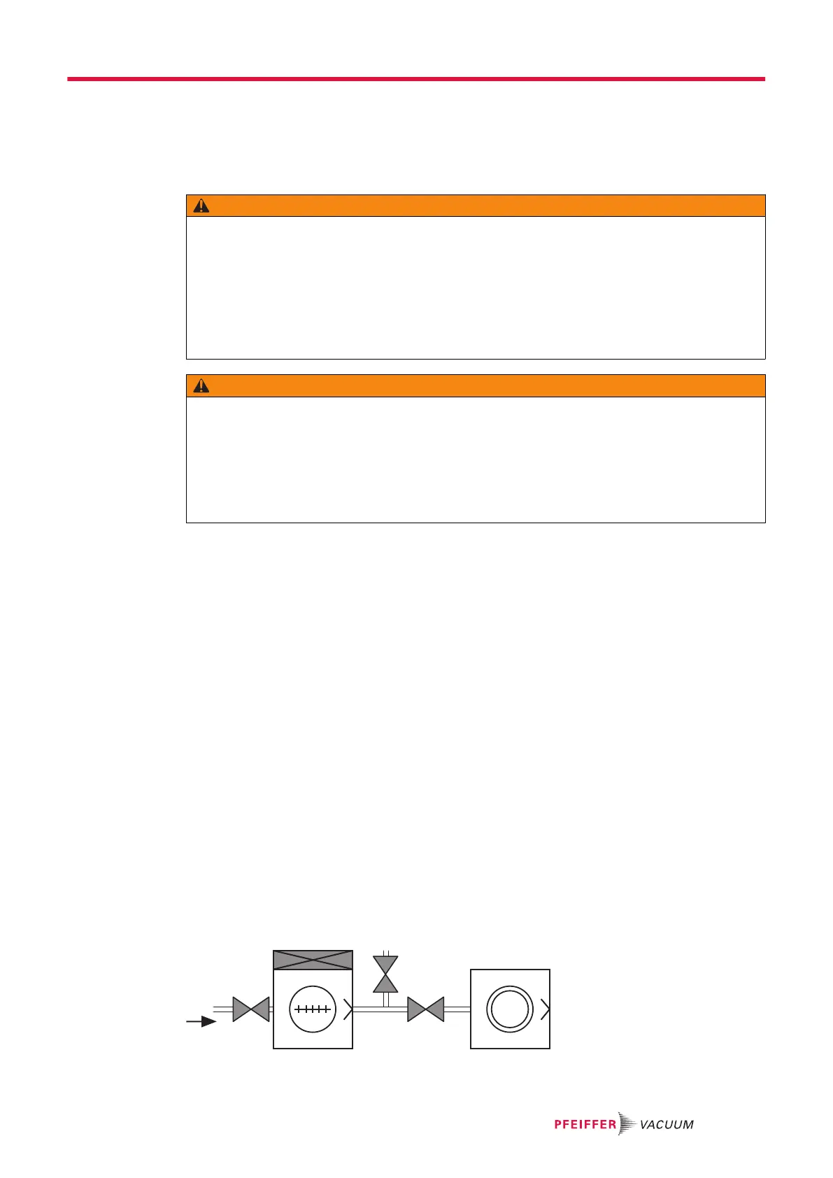
Fig. 5: Pumping installation diagram
Operation
25/60
 Loading...