V2
V4
V3
N2
V1
24VDC
W
W
Purge
Venting
Water
Heating/Braking
Turbo
1
2
11
2
4
Water
P
3
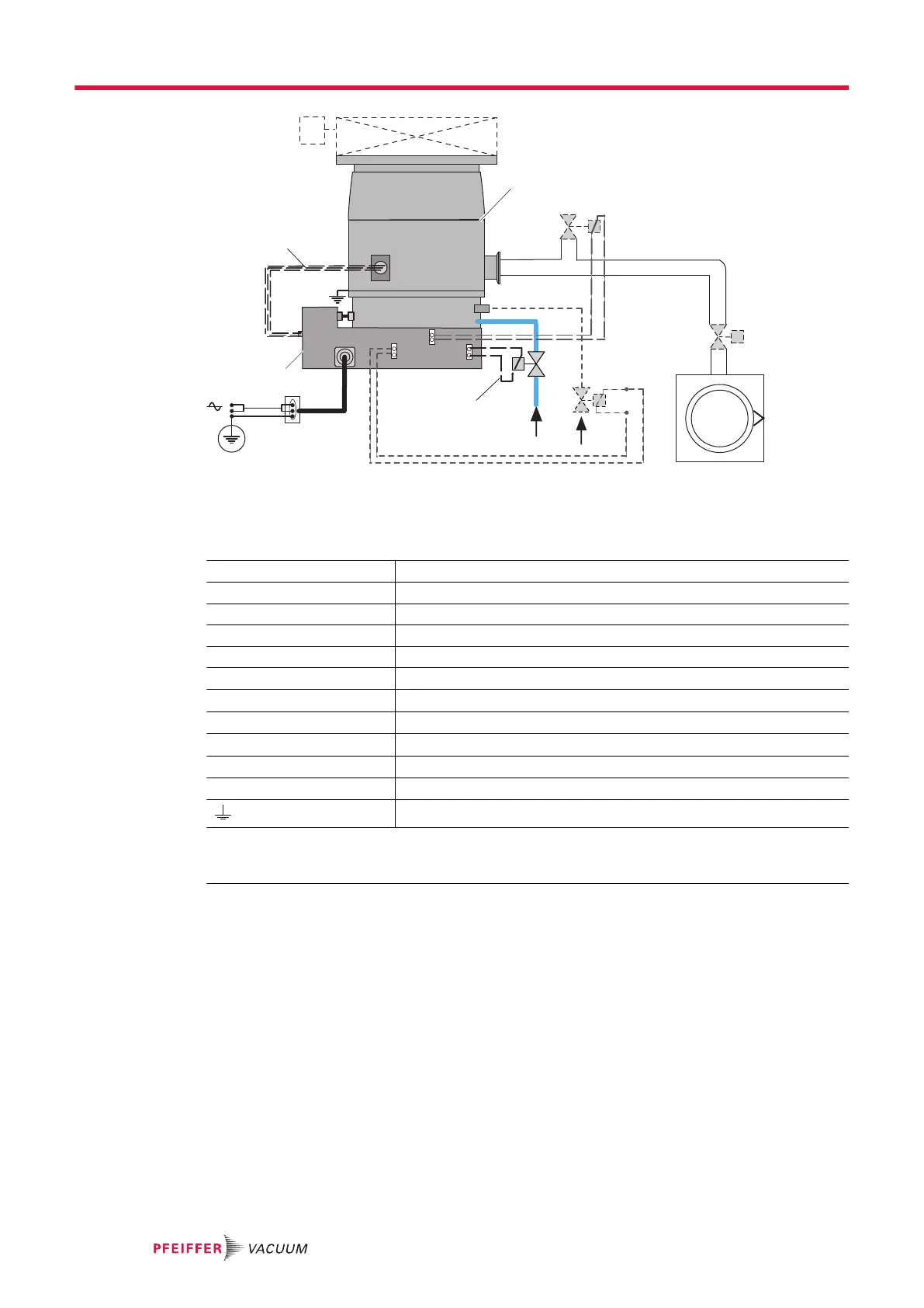
Fig. 4: Typical electrical wiring diagram
1 Heater band power supply (MT version pump)
2 Magnetically levitated turbomolecular pump
3 Water valve power supply (MT version pump)
4 Electronic drive unit
P Backing pump
N2 Inert gas input
V1
Fore-vacuum isolation valve
2)
V2
High vacuum isolation valve
2)
V3
Purge solenoid valve (option)
2)
V4
Air inlet solenoid valve (accessory)
2)
W Cooling circuit solenoid valve (MT version pump)
Functional ground connection
1)
1) Recommended for connecting the pump to the ground electrode in an environment affected by
electromagnetic waves.
2) These solenoid valves are controlled via the electronic drive.
Installation
24/60
 Loading...