8 Interfaces for control
8.1 Control modes
This chapter describes the connections and protocols associated with each control mode. There are 4
control modes:
●
HHR
The pump is controlled locally from a Hand-Held Remote control (HHR), connected on the SERV-
ICE connector.
●
REMOTE
The pump is controlled remotely by opening and closing different dry contacts or applying voltage
to the REMOTE connector.
●
SERIAL LINK
The pump is controlled remotely by the commands transmitted via serial link RS-232/RS-485.
●
FIELDBUS CONNECTION
The pump is controlled with a remote-control system (automation, control, supervision) that com-
municates with the pump according to the fieldbus communication protocol.
Different control interfaces for communication with fieldbuses (Profibus, EtherCAT, ... ) are availa-
ble in the ordering guide.
Choice of control mode
The selected mode controls the pump. The control mode can be selected:
●
via the HHR unit
●
via serial link RS-232/RS-485
8.2 Control via the HHR
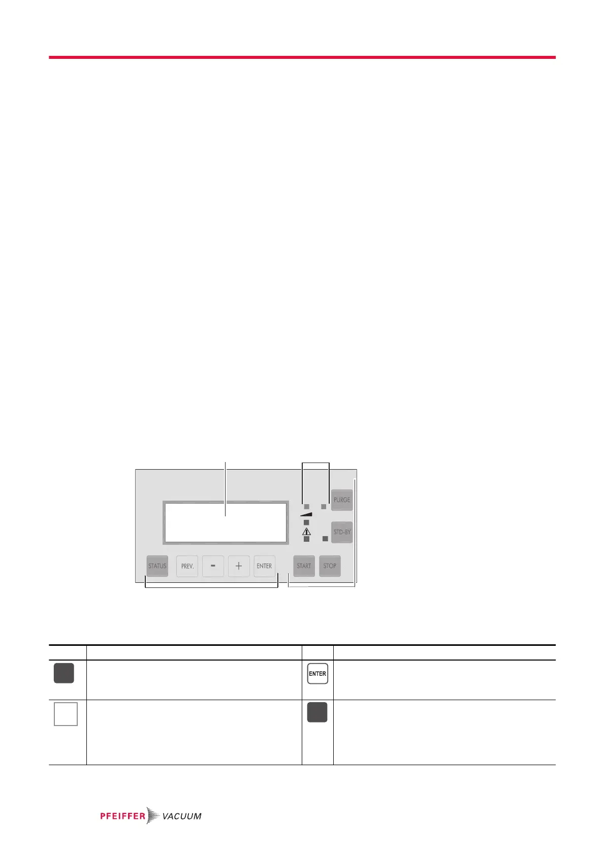
Description of the HHR
Connected to the electronic drive unit, the HHR allows to display and configure the pump parameters.
1 Display 3 Parameter selection and configuration keys
2 LED 4 Manual control keys
Key Functions Key Functions
● To access the parameter display mode.
● To exit the menus and return to parameter
display.
● To validate the selection of a menu, parameter,
or value.
● To confirm the answer to a question.
● To access the configuration mode.
● To exit the various menus without validating
the functions.
● To allow pump operation at reduced speed via
HHR when the [SET UP][REMOTE CONTROL]
menu is set to [KEYBOARD] (see chapter 'Me-
nu SETUP').
LED is lit when the pump rotates at Stand-by
speed.
Interfaces for control
30/60
 Loading...