5.4.3 Mains connection by a stuffing box
WARNING
Danger to life from electric shock in the event of a fault
In the event of a fault, devices connected to the mains may be live. There is a danger to life from
electric shock when making contact with live components.
►
Always keep the mains connection freely accessible so you can disconnect it at any time.
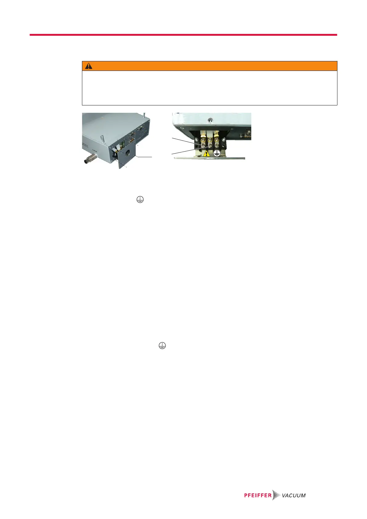
Fig. 3: Electrical connection by a stuffing box
1 Phase CPC Earth
2 Neutral 3 Screw (x4)
Procedure for electrical connection to the mains via a stuffing box
The electronic drive unit is designed for a fixed electrical connection, which prevents the cable from be-
ing pulled out. The installer is responsible for the supply and wiring.
1. Provide an electrical connection in accordance with protection rating IP54. The temperature of the
connection can reach 60 °C.
2. Remove the 4 screws and remove the front plate to access the terminal block.
–
Do not pull the plate excessively, otherwise the internal connections will be damaged!
3. Use an EEC cable in compliance with IEC 60227 and IEC 60245 standards with the following
characteristics:
–
cable diameter: 6 to 12 mm
–
heatproof (because it can come into contact with hot surfaces)
–
conducting wire section suitable for cable length (1.5 to 2.5 mm
2
)
–
current carrying capability: 10 A under 250 V
4. Connect the conducting wires to the terminal block.
5. Connect the protective earth (ground) wire to the terminal block.
6. Reattach the plate with the 4 screws to close it.
7. Conduct a test of continuity between the installation, the pump and the electronic drive unit.
The IEC 60417 #5019 symbol is located in the electronic module on the CPC earth terminal block.
5.4.4 Connecting the cables
According to the ordering guide, the pump can be equipped with a heater jacket and solenoid valves
(water, purge and inlet vent). These components are powered and controlled by the electronic drive
unit.
►
Remove the screws fastening the solenoid valves onto the electronic module.
►
Connect the VENTING cable to the air valve
►
Connect the PURGE cable to the purge valve
►
Connect the WATER cable to the water valve for MT version pumps
►
Connect the HEATING/BRAKING cable to the heater jacket for MT version pumps.
Installation
23/60
 Loading...