PEC Plus user manual What you need to know before installing your PEC Plus
31040003 13
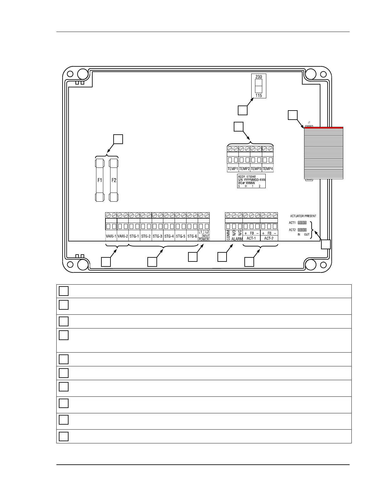
PEC Plus layout
Voltage selection switch – set this switch to the correct voltage before installing your PEC Plus.
Variable stage fuses (F1, F2) – 15 A, 250 VAC ABC-type ceramic; F1 variable stage 1, F2 for stage
2.
Variable stage terminals (VAR1, VAR2) – connect variable speed fans to these terminals.
General-purpose relay terminals (RLY1 to RLY6) – connect single stage (on/off) equipment to
these terminals. You can configure these relays as heat, cool, duty cycle, curtain, or actuator
control.
Incoming power terminal – connect the incoming power (120/230 VAC, 50/60 Hz) to this terminal.
Alarm relay terminal – connect an external alarm system or alarm siren to this terminal.
Actuator feedback terminals (ACT1 and ACT2) – connect the feedback from the actuators to these
terminals.
Actuator present pins (ACT1 and ACT2) – place the jumpers on the IN pins to enable, or on the
OUT pins to disable actuator control for the corresponding actuator.
Temperature probe terminals (TEMP1 to TEMP4) – connect the temperature probes to these
terminals. If monitoring outdoor temperatures, connect the outdoor probe to the TEMP4 terminal.
Display cable – make sure the ribbon cable from the display is properly connected to the socket.
10
9
8
7
6
5
4
3
2
1
9
1
2
3 4
5 6
7
10
8