Circuit Descriptions, Abbreviation List, and IC Data Sheets
EN 134 Q528.1E LA9.
Demodulation & Decoding DSP is used for demodulation and
decoding of all analogue terrestrial TV sound standards that
the TV520 platform covers.
The Audio Post-Processing DSP supports DPLII together with
volume and tone control, spatialisers, and equalizers for 6
channels (max.)
Digital Audio Decoder DSP is used to decode digital
compressed streams such as MPEG and AC-3. This runs as
SW Codecs on the AV-DSP.
9.6.3 Audio-Video Codec Subsystem
The AV Codec subsystem consists of the modules required to
capture and de-scramble Transport stream inputs together with
decoding of Audio/video Streams. Refer to figure “PNX8535
video flow diagram” for a clarification.
The sub-system consists of the following modules:
The Conditional Access Interface block provides a direct
interface towards a PCMCIA socket for Conditional Access. It
supports both the DVB CI-CA Specification and the CableCard
(POD) Interface.
The MPEG System Processor (VMSP) provides parsing an
MPEG-2 transport stream, including de-scrambling, de-
multiplexing and appropriate routing of data to the memory.
The Video MPEG Decoder (VMPG) performs MPEG2
decoding for both MP@ML and MP@HL streams.
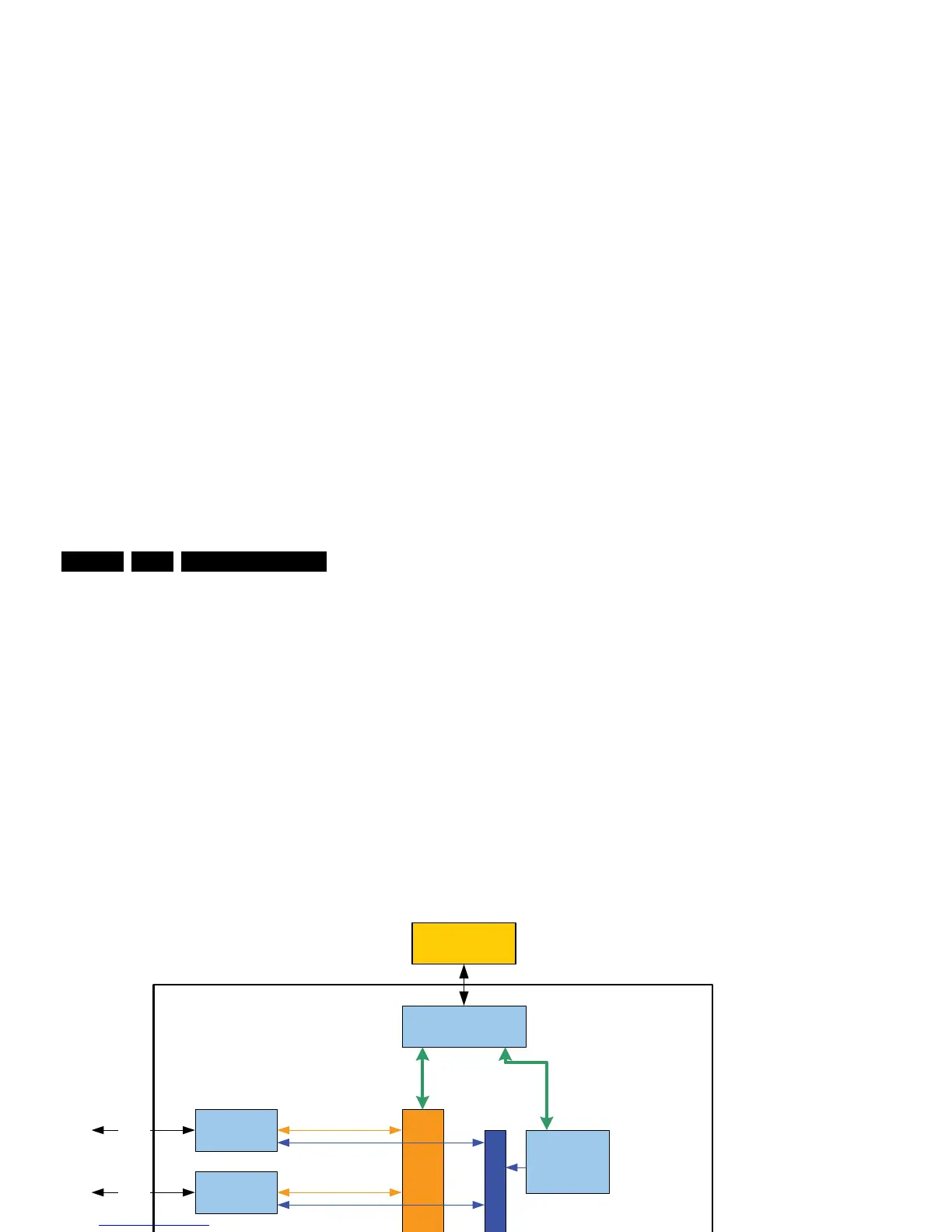
9.6.4 Control and Compute Subsystem
Refer to figure “Control and compute subsystem” for a
clarification of the blocks that are used in this device.
Figure 9-12 Control and compute subsystem
The Control and compute subsystem consists of the main
processor, control peripherals and the memory system.
The MIPS 4KEc is a 32-bit MIPS RISC core. It has direct
access to connectivity peripherals to support system features
via PCI, I
2
C, UART or General Purpose I/O. A JTAG interface
provides processor software debug capabilities.
The Memory Control Unit (MCU) is a 32-bit DDR2 SDRAM
interface supporting DDR2-533 with an address range of 128
MB (max.).
The PCI/XIO interface supports PCI Rev2.2 and can be used
to access 8/16-bit external NAND-Flash memory.
H_16770_126.eps
270307
D
C
S
-
N
e
t
w
o
r
k
I2C-3
MCU
D
M
A
B
u
s
PNX8535
DDR2-SDRAM
I2C-DMA3
I2C-2 I2C-DMA2
PCI/XIO
PCI/XIO
2-wire UART1
2-wire UART2
MIPS
MTI-4KeC
System
Controller
80C51
I2C-4
UART-3
PWM’s
GPIO’s
CAI
CA
I2C-1 I2C-Slave
E-JTAG
E-JTAG
DMA