Circuit Descriptions, Abbreviation List, and IC Data Sheets
EN 136 Q528.1E LA9.
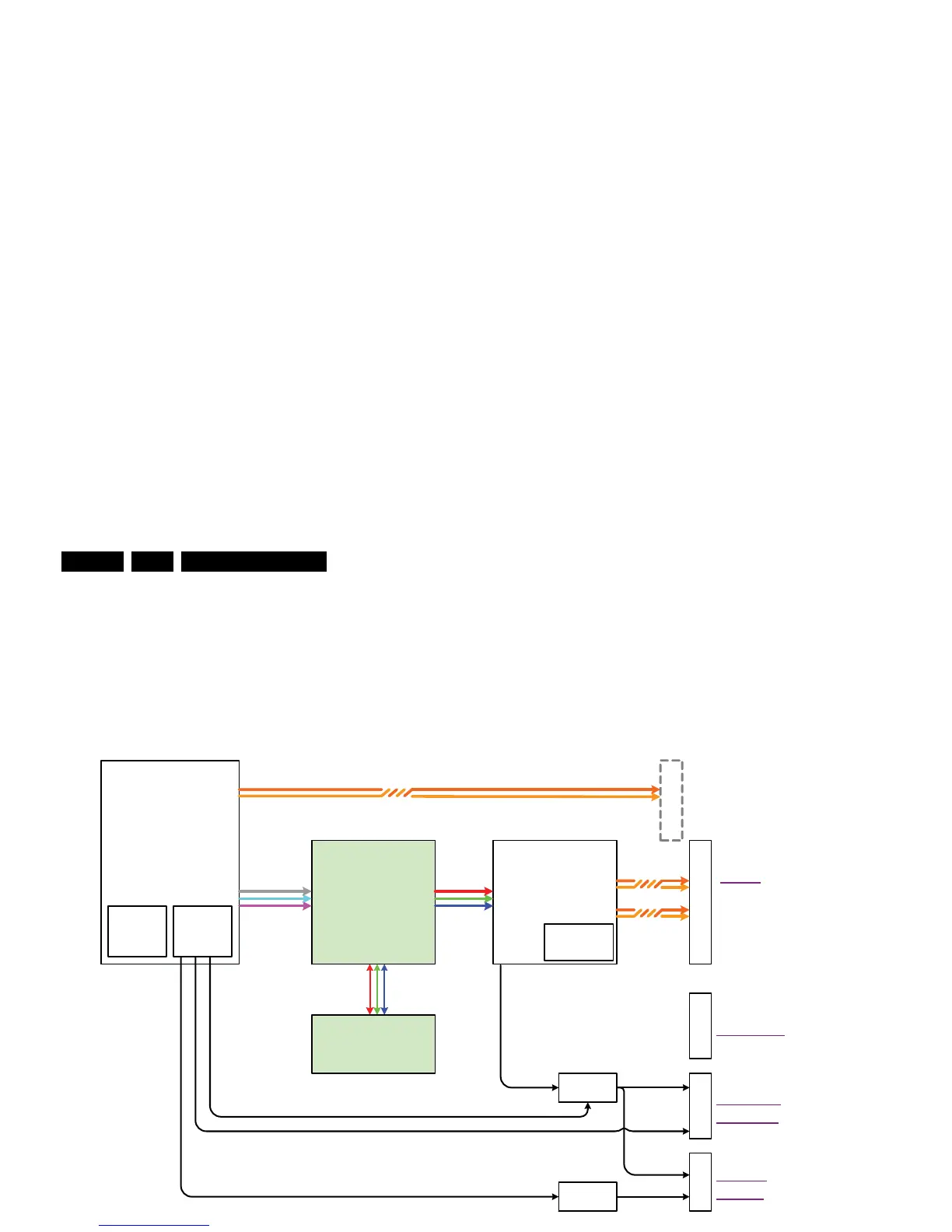
9.7.2 Full-HD sets @ 50 / 100 Hz
In full-HD sets @ 50 / 100 Hz, the output signal coming from the
PNX8535 is fed to the PNX5050 and then to the PACIFIC 3.
The PACIFIC 3 also generates the pulse-width modulated
signal needed for the “Dimming Backlight” feature, which
ensures additional motion sharpness. As some displays
require an analogue signal to switch the LCD, a multiplexer is
added to transform the puls-width modulated signal. An
additional signal, coming from the PNX8535, makes the
selection between analogue and pulse-width modulation,
depending on which display is used. Scanning Backlight
displays require an analogue signal, and all other displays a
pulse-width modulated. The signal for “Scanning Backlight” is
an I
2
C signal coming from the PNX8535.
Refer to figure “Block diagram display control Full-HD sets 50 /
100 Hz”.
Figure 9-14 Block diagram display control Full-HD sets 50 / 100 Hz
H_16770_130.eps
270307
PNX5050
LVDS 41p - FI-R41S-HF
1M591D42
LVDS
fHD
fHD 2fv
with DFI
Pacific 3
SPI -flash
M25 P 05 -AVM N 6 P
9322 206 45668
PNX8535
M2
AmbiLight
Scanning
Backlight
1S01
Display
Supply
I2C-Scanning ( no dimm ing )
PW M (Anal og )
Dimming
LVDS FI-WE31P-HF
Debugging only !!
Select -AnaPW M Di mmi ng
Converter
+
MUX
PWM
Dimming
2x DDR
Analog (PW M )
Dimming
MIPS StdBy
PWM Boost
Converter
Analog Boost
YUV
10b
RGB
10b
LVDS
10b
LVDS
10b