Service Modes, Error Codes, and Fault Finding
EN 22 Q528.1E LA5.
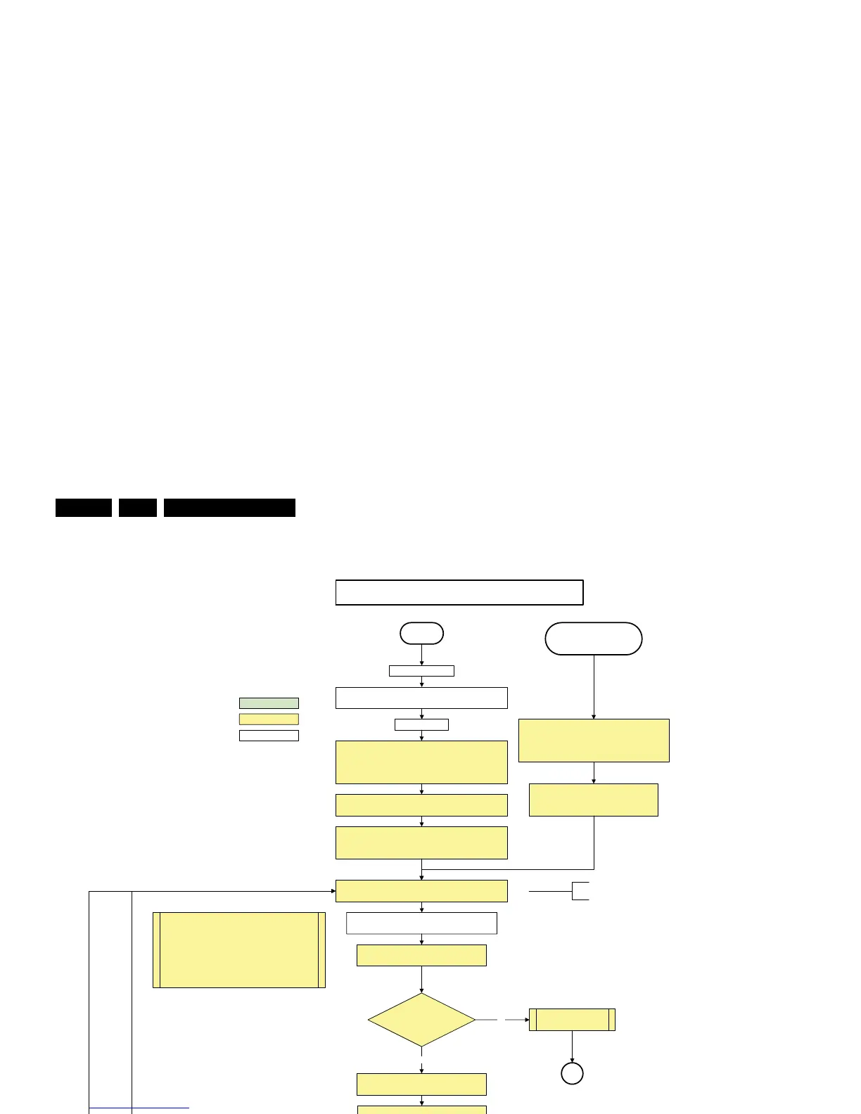
Figure 5-4 “Off” to “Semi Stand-by” flowchart (part 1)
All I/O lines have a High default state:
- Switch PNX8535 in reset (active LOW).
- Keep the Audio-reset high.
- NVM power line is high, no NVM communication possible.
Off
Standby Supply starts running.
All standby supply voltages become available .
st-by µP resets
action holder: MIPS
autonomous action
action holder: St-by
Stand by or
Protection
Mains is applied
- Switch Audio-Reset high.
It is low in the standby mode if the standby
mode lasted longer than 10s.
No
Yes
SP
“5V 12V supply” error
detect-5V-12V received within
2900 ms after POD-mode I/O
line toggle?
No
SP
Yes
Detection
received within
250 ms after enable-3V3
toggle?
+5V, and +12V are switched on
No
SUPPLY-FAULT I/O line
is High ?
Switch ON Platform and display supply by switching LOW the
POD-MODE and the ON-MODE I/O lines .
Initialise I/O pins of the st-by µP, start keyboard scanning, RC
detection. Wake up reasons are off.
If the protection state was left by short circuiting the
SDM pins, detection of a protection condition during
startup will stall the startup. Protection conditions in a
playing set will be ignored. The protection mode will
not be entered.
PDPGO line is high (either HW wise in a non FHP set or
because of the stby µP reset in an FHP set) which will start the
FHP PDP.
Wait 50ms and then start polling the detect-
5V-12V every 40ms.
The availability of the supplies is checked through detect
signals going to the st-by µP. These signals are available
for +12V and +5V (combined as AND function, called
detect-5V-12V ) and for +1V2 and +3V3 (combined as
AND function, called detect -1V2-2V5-3V). A low to high
transition of the signals should occur within a certain time
after toggling the standby line. If an observer is detected
before the time-out elapses, of course, the process
should continue in order to minimize start up time.
No separate enable is present
for the +1V8 supply in the
TV520.
Only one detect line is present
in the TV520: it detects +1V2
and +3V3
50ms is used in the Jaguar platform.
100ms is recommended by the
PNX8535 spec.
The supply fault line is an OR
function of DCDC, DCDC5050
and POD/CI supply switch .
Display supply is switched on
through the ON-mode I/O line
activate +5V/+12V supply
detection algorithm. See CHS protections.
Off/Stby to Semi
Enable the +1V2 supply (ENABLE-1V2)
Wait 100ms
Enable the supply for
+1.8V and +3.3V (ENABLE-3V3)
Start polling the detect-1V2-2V5-3V3
every 40ms
1V2 2V5 3V3 DCDC error
Activate supply detection algorithms for DC-
DC outputs
Wait 20ms
Supply fault error
H_16770_109a.eps
110507