Mechanical Instructions
EN 14 Q528.1E LA4.
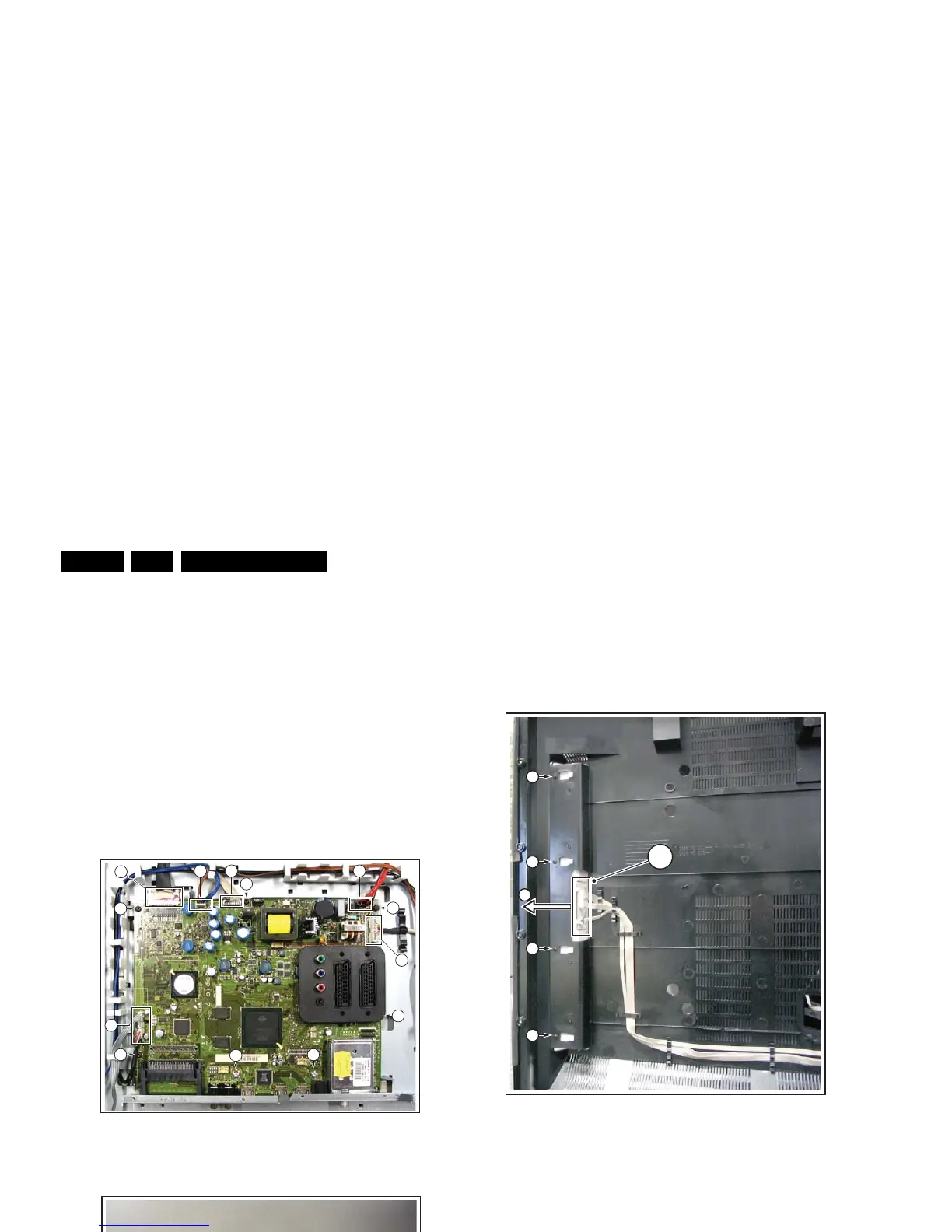
4.3.8 Small Signal Board (SSB)
Caution: it is mandatory to remount all different screws at their
original position during re-assembly. Failure to do so may result
in damaging the SSB.
Refer to next figures or details.
1. Remove the tapping screws [1].
2. Unplug the connectors [2].
3. Unplug the LVDS connector [3]. Caution: be careful, as
this is a very fragile connector!
The SSB can now be taken out of the set, together with the
front shield.
To remove the shield:
4. Remove the parker screws [4].
5. Remove the tapping screws [5].
6. Remove the shield from the SSB.
Figure 4-19 Small Signal Board -1-
Figure 4-20 Small Signal Board -2-
4.3.9 AmbiLight Unit
The AmbiLight Units are located in the back cover. Refer to
next figure for details.
1. Remove the screws [1].
2. Unplug the connectors [2].
3. Slide the unit sideways and take it out of the backcover.
Figure 4-21 AmbiLight Unit
When defective, replace the whole unit.
4.3.10 LCD Panel
Refer to next figures for details.
1. Take the speakers out as earlier described.
2. Remove the LED/IR panel.
3. Unplug the connector [1].
4. Remove the Display Supply Panel, as earlier described.
5. Remove the parker screws [2].
6. Remove the tapping screws [3].
7. Unplug the LVDS connector [4] from the LCD panel.
Important: Be careful, as this is a very fragile connector!
8. Remove the cables out of their bracket [5].
9. Remove the fixation screw [6] from the side I/O panel.
10. Lift the central sub-frame from the set.
11. Lift the LCD panel from the front cabinet.
H_16800_119.eps
110507
1
1
1
1
1
1
1
3
2 2
2
2
2
H_16800_120.eps
090507
555
44
H_16770_094.eps
220307
2
1
1
3
1
1