Circuit Descriptions, Abbreviation List, and IC Data Sheets
EN 146 Q528.1E LA9.
9.10 IC Data Sheets
This section shows the internal block diagrams and pin
configurations of ICs that are drawn as "black boxes" in the
electrical diagrams (with the exception of "memory" and "logic"
ICs).
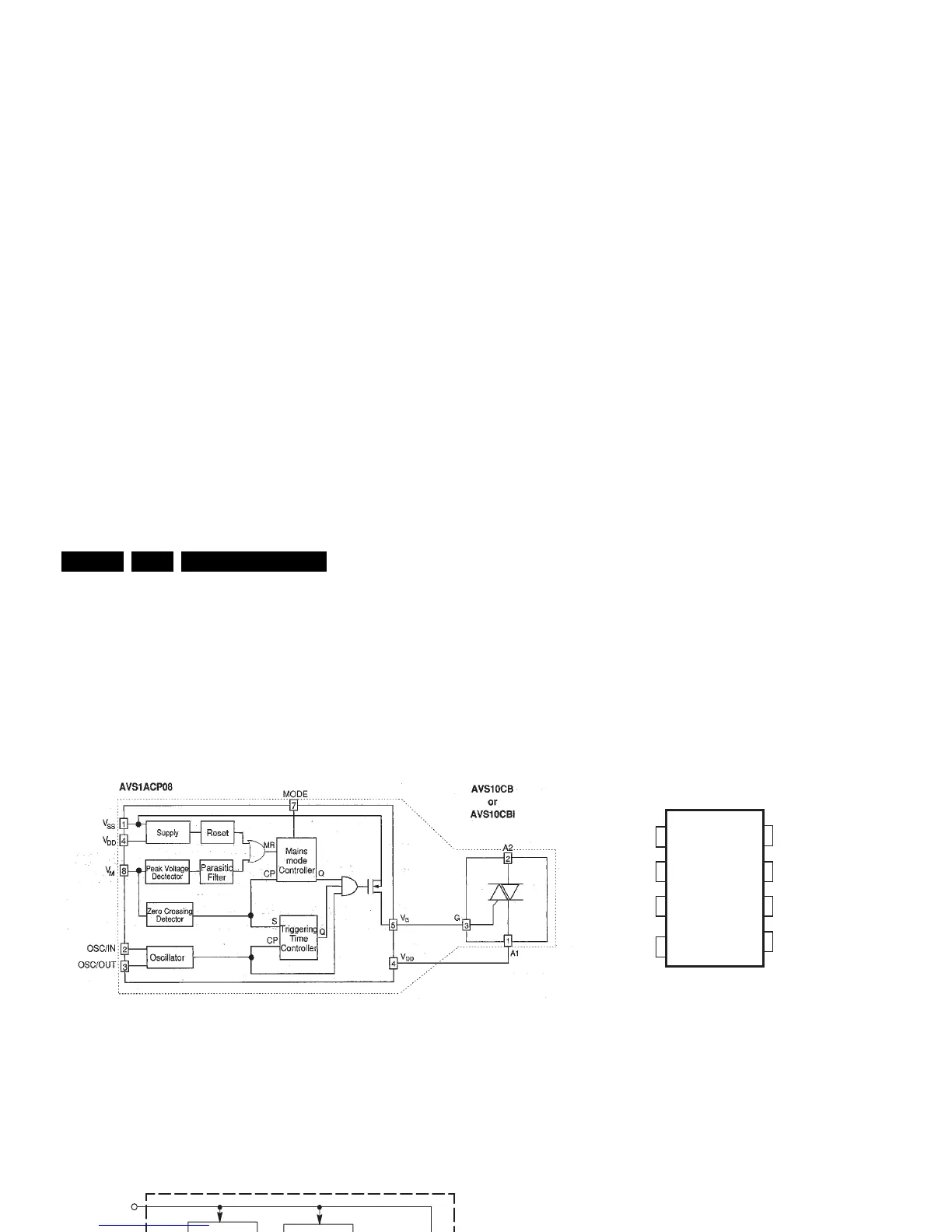
9.10.1 Diagram A1, AVS1ACP08 (IC 7305)
Figure 9-23 Internal block diagram and pin configuration
9.10.2 Diagram A2, MC34067P (IC 7001)
Figure 9-24 Internal block diagram and pin configuration
BLOCK DIAGRAM
E_14620_145.eps
230905
1
2
3
4
8
7
6
5
PIN CONFIGURATION
VSS
Osc/In
Osc/Out
V
DD
VM
Mode
N.C.
V
G
1
2
3
4
5
6
7
8
16
15
14
13
12
11
10
9
(Top View)
V
ref
Osc Charge
Osc RC
Osc Control Current
Gnd
Error Amp Out
Inverting Input
Noninverting Input
One–Shot RC
V
CC
Drive Output B
C
Soft–Start
Enable/UVLO
Adjust
Drive Output A
Power Gnd
Fault Input
Noninverting
Input
11
8
6
16
3
2
1
Osc Charge
Enable /
UVLO Adjust
V
CC
15
5
14
12
13
V
ref
UVLO
Error
Amp
V
CC
UVLO /
Enable
Fault Detector
2.5 V
Clamp
Soft–Start
One–Shot
Output B
Inverting Input
Soft–Start
7
Error Amp
Output
One–Shot
Oscillator
Control Current
Osc RC
9
Ground4
Fault Input
10
Pwr Gnd
Output A
V
ref
Variable
Frequency
Oscillator
Steering
Flip–Flop
5.0 V
Reference
Block Diagram
MC34067
Pin Configuration
F_15710_163.eps
230905