Circuit Descriptions, Abbreviation List, and IC Data Sheets
EN 142 Q528.1E LA9.
9.8 Ambient Light
In this chassis, LED AmbiLight units are introduced as the
successor of CCFL AmbiLight units. The system that is used is
called “LUMILED”.
The units are completely aligned in factory and are a “Black
Box” for Service. When defective, they must be replaced
entirely. Refer to the Spare Parts List for the correct order
number.
The AmbiLight units are addressed by I
2
C. The I
2
C-address for
all lamp units is “6A”. To address each unit separately,
selection lines are needed to distinguish between the boards.
Control is done by the SSB. Refer to figure “Ambient Light block
diagram” for details.
Figure 9-20 Ambient Light block diagram
To address a specific unit, the selection line has to be “low”.
In case of 2-sided AmbiLight, 6 data bytes are used to address
the units, 3 bytes for each lamp unit. They are driven by Pulse
Width Modulation (PWM). Refer to figure “Lamp unit
addressing” for details.
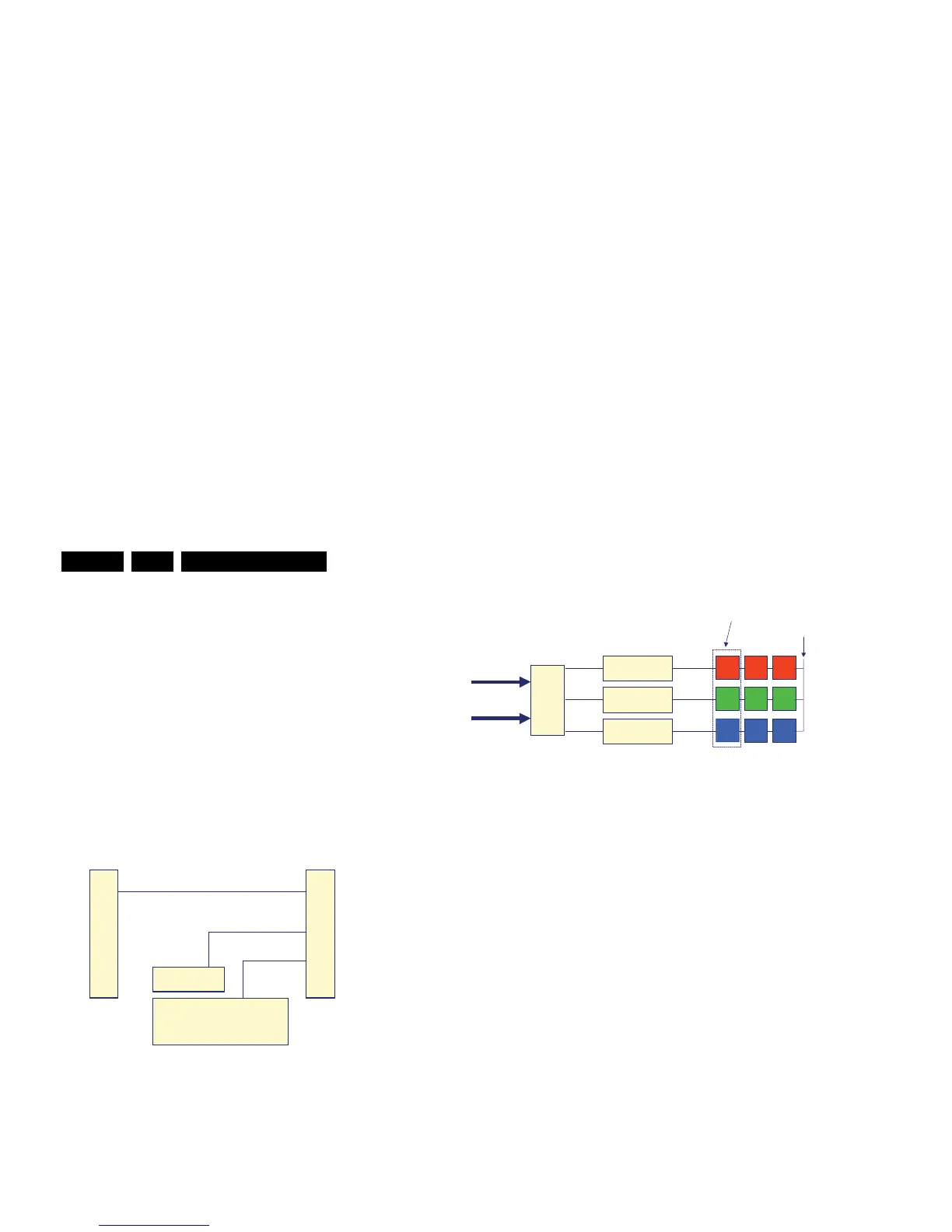
Figure 9-21 Lamp unit addressing
The driver current is different for the “basic colours” (R, G and
B) of each LED package. The “red” and “blue” LED’s of each
package need a driver current of 150 mA, the “green” LED
need a driver current of 200 mA. Refer to figure “Ambient Light
module driving” for details. Each unit need a 12 V supply to
drive the LED’s.
Figure 9-22 Ambient Light module driving
The configuration shown in figure “Ambient Light module
driving” is implemented two times per module.
H_16770_139.eps
280307
TV520 SSB
(= I
2
C AmbiLight master)
FirstSecond AmbiLight Unit AmbiLight Uni