Service Modes, Error Codes, and Fault Finding
EN 33Q528.1E LA 5.
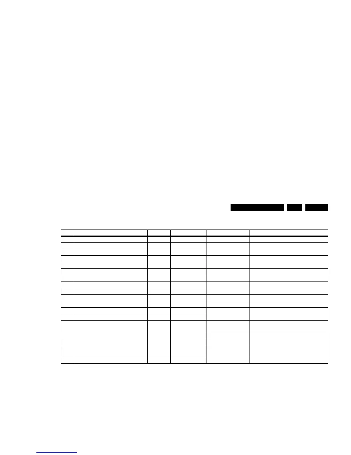
Table 5-3 Error code overview
Note
1). Where applicable.
Extra Info
• Rebooting. When a TV is constantly rebooting due to
internal problems, most of the time no errors will be logged
or blinked. This rebooting can be recognized via a ComPair
interface and Hyperterminal (for Hyperterminal settings,
see paragraph “Stand-by software upgrade). You will see
that the loggings which are generated by the main software
keep continuing. In this case (rebooting) diagnose has to
be done via ComPair.
• Error 3 (I
2
C bus 3 blocked). At the time of release of this
manual, this error was not working as expected (error 3 is
logged and can be read out). Current situation: when this
error occurs, the TV will constantly reboot due to the
blocked bus. The best way for further diagnosis here, is to
use ComPair (e.g. read out the NVM content). Instead of
error “3” it is possible you will see error “2” in the error
buffer.
• Error 5 (PNX8535 doesn’t boot). Indicates that the main
processor was not able to read his bootscript. This error will
point to a hardware problem around the PNX8535
(supplies not OK, PNX 8535 completely dead, I
2
C link
between PNX and Stand-by Processor broken, etc...).
When error 5 occurs it is also possible that I
2
C2 bus is
blocked (NVM). I
2
C2 can be indicated in the schematics as
follows : SCL-UP-MIPS, SDA-UP-MIPS, SCL-SLAVE,
SDA-SLAVE, SCL-2 or SDA-2.
• Error 11 (I
2
C MUX1). Indicates a blocked (short-circuited)
I
2
C-MUX1 bus. At the time of release of this manual, this
error was not working as expected.
• Error 12 (I
2
C MUX2). Indicates a blocked (short-circuited)
I
2
C-MUX2 bus. At the time of release of this manual, this
error was not working as expected.
• Error 24 (I
2
C switch). As a side effect of error 24 it is
possible that error 47(no existing error) will also be logged.
• Error 28 (DFI Ambilight MOP). It can take up to 2 minutes
or more before this error is logged. So if you suspect that
this MOP is defective: clear the error buffer, restart the TV
and wait for about 2 minutes before checking the error
buffer.
• Error 37 (Channel decoder). When this error occurs,
there probably will be no picture and sound from tuner
input. As a side effect of error 37 it is possible that error 4
(no existing error) is also logged.
• Error 46 (Pacific 3). When there is an actual problem with
or around the Pacific during start-up, you will have no
picture and error 46 will be blinked via the blinking LED
procedure. For further diagnosis you can always dump the
CSM content on USB stick (see CSM) or use ComPair.
• Error 53. This error will indicate that the PNX8535 has
read his bootscript (if this would have failed, error 5 would
blink) but initialization was never completed because of
hardware problems (NAND flash, ...) or software
initialization problems. Possible cause could be that there
is no valid software loaded (try to upgrade to the latest main
software version). Note that it can take up to 2 minutes
before the TV starts blinking error 53.
• Error 63 (POWER OK). When this error occurs, it means
that the POWER-OK line did not became “high”. This error
is only applicable for TV’s with an LCD display. For PDP
displays there will be no protection during a POWER-OK
line failure, but error 63 will be logged in the error buffer.
Caution: in case a PDP TV ends up into power-ok
protection, it can indicate that the display option code is set
to “LCD”. To change the display option code to “PDP” you
need to activate SDM via the service pads (see figure
“Service mode pads”). Then change the display option
code blindly via a standard RC : key in the code “062598”
directly followed by the “MENU” button and “XXX” (where
XXX is the 3 digit decimal display option code as
mentioned in figure “Display option code overview”).
• Error 65 (DFI EPLD error). When this error occurs it
means that there is a problem with the I
2
C communication
towards the EPLD (picture processing EPLD, not the
Ambilight EPLD) on the DFI panel.
5.6 The Blinking LED Procedure
5.6.1 Introduction
The blinking LED procedure can be split up into two situations:
• Blinking LED procedure in case of a protection. In this case
the error is automatically blinked. This will be only one
error, namely the one that is causing the protection.
Therefore, you do not have to do anything special, just read
out the blinks. A long blink indicates the decimal digit, a
short blink indicates the units.
• Blinking LED procedure in the “on” state. Via this
procedure, you can make the contents of the error buffer
Error Description Error/Prot Detected by Device Result
3I
2
C3 E MIPS PNX8535 Error logged
5 PNX8535 does not boot (HW cause) E Stby P PNX8535 Error blinking
6 5V, 12V supply P Stby P / Protection + Error blinking
8 1V2, 1V4, 2V5, 3V3 supply P Stby P / Protection + Error blinking
9 Supply fault P Stby P / Protection + Error blinking
11 I
2
C-MUX1 E MIPS PCA9540 Error logged
12 I
2
C-MUX2 E MIPS PCA9540 Error logged
22 PNX5050 E MIPS PNX5050 Error logged
23 HDMI mux E MIPS AD8190/AD8191 Error logged
24 I
2
C switch E MIPS PCA9540 Error logged
26 Master IF E MIPS TDA9898/9897/9890 Error logged
28 MOP (Ambilight MOP on DFI panel)
1)
E MIPS EP2CXXF484C7N Error logged
34 Tuner E MIPS TD1716 Error logged
37 Channel decoder E MIPS TDA10060/
TDA10048
Error logged
46 Pacific3 E MIPS T6TF4 Error blinking + Error logged
53 PNX 8535 does not boot (SW cause) E Stby P PNX8535 Error blinking
63 Power OK E/P MIPS / Error logged in case of a PDP set
Protection in case of an LCD set
65 DFI (EPLD on DFI panel)
1)
E MIPS / Error blinking + Error logged