FL MGUARD RS2000 TX/TX-B
105656_en_05 PHOENIX CONTACT 107
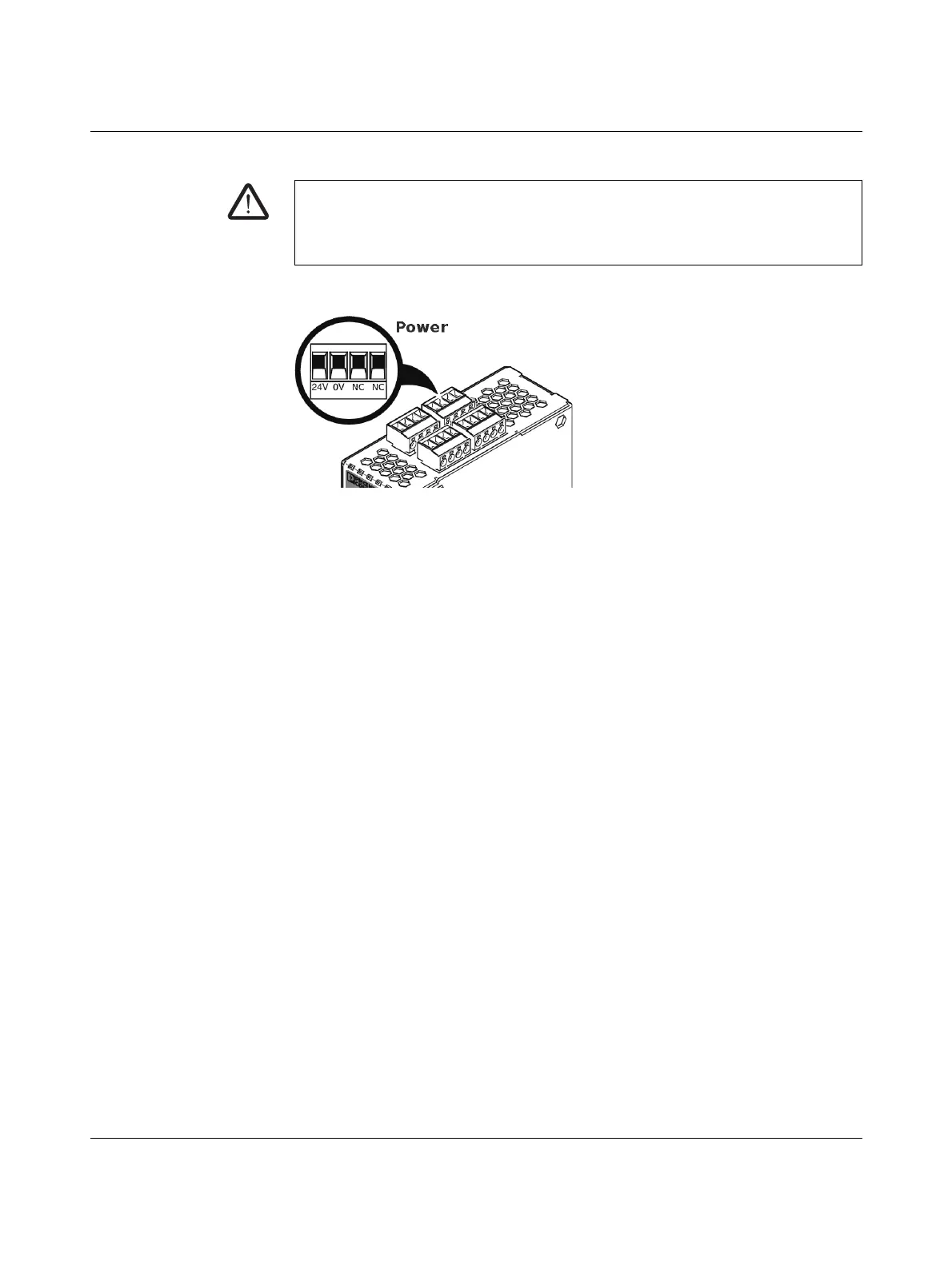
5.3.4 Connecting the supply voltage
The supply voltage is connected via a plug-in screw terminal block, which is located on the
top of the device.
Figure 5-4 Connecting the supply voltage
Instead of the designation 24V the designation US1 is also used.
Status LED P1 lights up green when the supply voltage has been connected properly.
The device boots the firmware. Status LED STAT flashes green. The device is ready for op-
eration as soon as the Ethernet socket LEDs light up. Additionally, status LED P1 lights up
green and status LED STAT flashes green at heartbeat.
WARNING: The FL MGUARD RS4000/RS2000 is designed for operation with a DC volt-
age of 11 V DC ... 36 V DC/SELV, 1.5 A, maximum.
Therefore, only SELV circuits with voltage limitations according to EN 60950-1 may be
connected to the supply connections and the signal contact.
 Loading...