FL MGUARD DELTA TX/TX
250
PHOENIX CONTACT 105656_en_05
12.3 Connecting the FL MGUARD DELTA TX/TX
12.3.1 Connecting to the network
• Connect the device to the network. To do this, you need a suitable UTP cable (CAT5)
which is not included in the scope of supply.
• Connect the internal network interface LAN 1 of the device to the corresponding Ether-
net network card of the configuration computer or a valid network connection of the in-
ternal network (LAN).
12.3.2 Connecting the supply voltage
• Connect the wide-range power supply unit of the device to a suitable power supply.
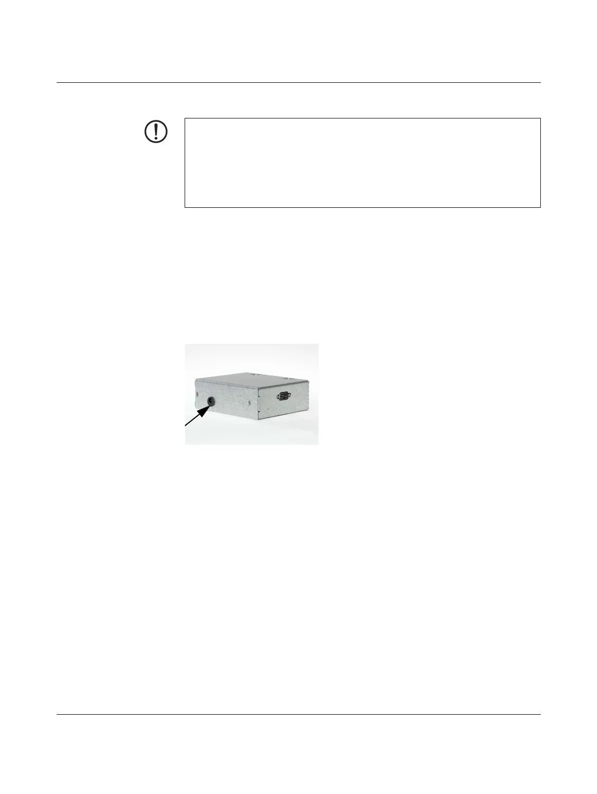
Connect the low-voltage plug of the power supply unit on the back of the device.
Figure 12-3 Low-voltage plug of the power supply unit
The status LED PWR lights up green when the supply voltage has been connected properly.
The device boots the firmware. Status LED STAT flashes green.
The device is ready for operation as soon as the LAN/WAN LEDs of the Ethernet socket
light up.
Additionally, the status LED PWR lights up green and the status LED STAT flashes green
at heartbeat.
NOTE: Notes on mounting and installation
Only connect the RJ45 Ethernet ports of the device to matching network installations.
Some telecommunications connections also use RJ45 sockets. You may not connect
these to the RJ45 ports of the device.
Safe isolation of live circuits is only guaranteed if connected devices fulfill requirements
specified by VDE 0106-101 (safe isolation). The supply lines must be isolated or laid sep-
arately to live circuits.
 Loading...