FL MGUARD PCI(E)4000
198
PHOENIX CONTACT 105656_en_05
9.3 Installation of FL MGUARD PCI4000
9.3.1 Installing the hardware
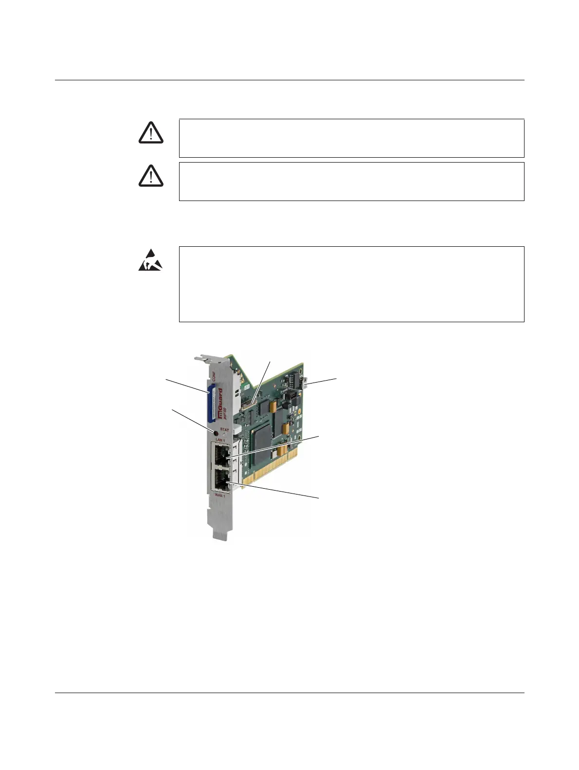
FL MGUARD PCI4000: structure
Figure 9-3 FL MGUARD PCI4000 structure
• Install the FL MGUARD PCI4000 in a free PCI or PCI Express slot. Observe the notes
in the documentation for your system.
WARNING: This is a Class A item of equipment. This equipment can cause radio interfer-
ence in residential areas; in this case, the operator may be required to implement appro-
priate measures.
WARNING: Safe isolation of live circuits is only guaranteed if connected devices fulfill re-
quirements specified by VDE 0106-101 (safe isolation). The supply lines must be isolated
or laid separately to live circuits.
NOTE: Electrostatic discharge
Before installation, touch the metal frame of the PC in which the FL MGUARD PCI4000 is
to be installed, in order to remove electrostatic discharge.
The device contains components that can be damaged or destroyed by electrostatic dis-
charge. When handling the device, observe the necessary safety precautions against
electrostatic discharge (ESD) according to EN 61340-5-1 and IEC 61340-5-1.
SD card slot (configuration
memory)
Reset button
RJ45 socket (LAN 1) for connecting to the in-
ternal network
Use a UTP cable (CAT5). The cable is not
supplied as standard.
RJ45 socket (WAN 1) for connecting to the
external network/Internet.
Use a UTP cable (CAT5). The cable is not
supplied as standard.
Battery (can be replaced)
Extension connection (LEDs, Reset button, SD card)
 Loading...