FL MGUARD RS4000 TX/TX VPN-M
144
PHOENIX CONTACT 105656_en_05
7.1 Operating elements and LEDs
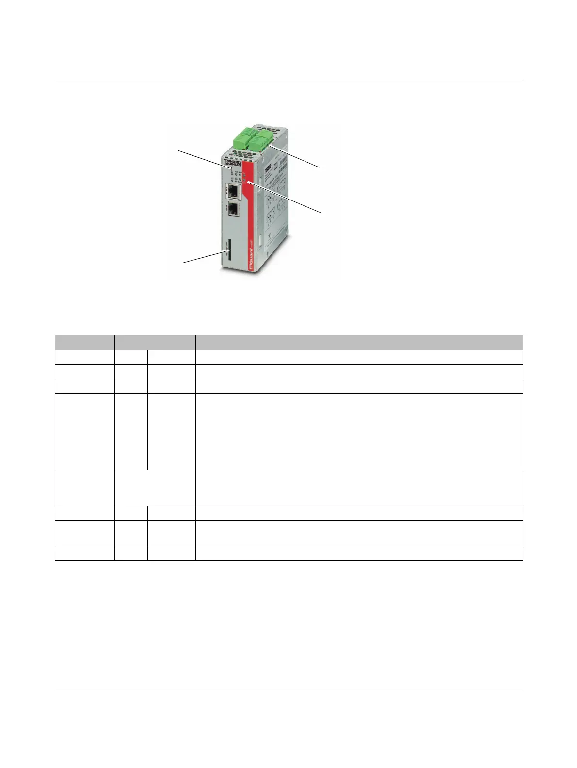
Figure 7-2 Operating elements and LEDs on the FL MGUARD RS4000 TX/TX VPN-M
LEDs, see Table 7-2
For plug-in screw terminal
blocks, assignment, refer to
Page 148 and Page 151
Configuration
(SD card)
Connections below:
RS-232 interface
Reset button
Table 7-2 LEDs on the FL MGUARD RS4000 TX/TX VPN-M
LED State Meaning
P1 Green On Power supply 1 is active
P2 Green On Power supply 2 is active
STAT Green Flashing Heartbeat. The device is correctly connected and operating.
ERR Red Flashing System error. Restart the device.
– Press the Reset button (for 1.5 seconds).
– Alternatively, briefly disconnect the device power supply and then connect it
again.
If the error is still present, start the recovery procedure (see Page 160) or contact your
dealer.
STAT+ E RR Flashing alter-
nately: green and
red
Boot process. When the device has just been connected to the power supply. After
a few seconds, this LED changes to the heartbeat state.
SIG –(Not used)
FAULT Red On The signal output changes to the low level due to an error (inverted control logic) (see
Page 150). The signal output is inactive during a restart.
MOD Green On Connection via modem established
 Loading...