FL MGUARD GT/GT
105656_en_05 PHOENIX CONTACT 171
8.3 Installation of FL MGUARD GT/GT
8.3.1 Mounting/removal
Mounting The device is ready to operate when it is supplied. The recommended sequence for mount-
ing and connection is as follows:
• Pull out the terminal block from the bottom of the FL MGUARD GT/GT and wire the con-
nections as required.
• Tighten the screws on the screw terminal blocks with at least 0.22 Nm.
Wait to insert the terminal block base.
• Mount the FL MGUARD GT/GT on a grounded 35 mm DIN rail according to
DINEN60715.
The device is grounded by snapping it onto a grounded DIN rail.
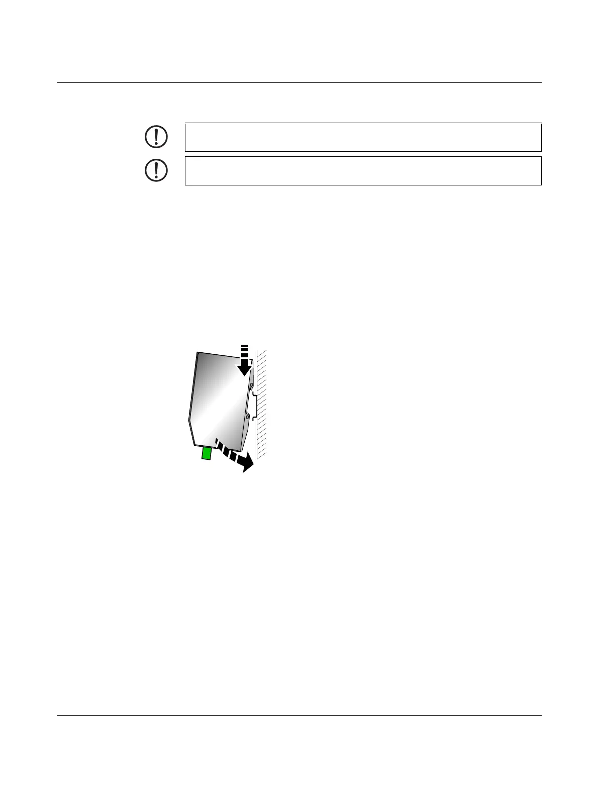
Figure 8-4 Mounting the FL MGUARD GT/GT on a DIN rail
• Attach the top snap-on foot of the FL MGUARD GT/GT to the DIN rail and then press
the FL MGUARD GT/GT down towards the DIN rail until it engages with a click.
• Insert the required wired terminal blocks.
• Make any necessary network connections at the LAN port or WAN port (see “Connect-
ing to the network” on page 172).
• Connect the corresponding device at the serial port as required (see “RS-232 interface
for external management” on page 180).
Removal • Remove or disconnect the connections.
• To remove the FL MGUARD GT/GT from the DIN rail, insert a screwdriver horizontally
in the locking slide under the housing, pull it down – without tilting the screwdriver – and
then pull up the FL MGUARD GT/GT.
NOTE: The housing must not be opened.
NOTE: The shielding ground of the connected twisted pair cables is electrically connect-
ed to the front plate.
 Loading...