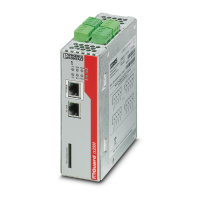
FL MGUARD CENTERPORT
234
PHOENIX CONTACT 105656_en_05
To configure the device via the serial interface. There are two options:
– A PC is connected directly to the serial interface of the device (via the serial interface of
the PC). The PC user can then use a terminal program to configure the device via the
command line.
– Or a modem is connected to the serial interface of the device. This modem is connected
to the telephone network (fixed-line or GSM network). The user of a remote PC, which
is also connected to the telephone network via a modem, can then establish a PPP
(Point-to Point Protocol) dial-up line connection to the device and configure it via a web
browser.
To manage data traffic via the serial interface instead of via the WAN interface of the de-
vice. In this case, a modem should be connected to the serial interface.
11.3.3 Installation in a 19" frame/industrial cabinet
The mains connecting cables of the power supply units are used as mains disconnect
points. Sockets that can easily be accessed and that are close to the device must therefore
be used for the mains plug. Unplug the mains plug to disconnect the device from the mains.
If the device is installed in a control cabinet where the sockets cannot be accessed, an ad-
equate disconnecting device must be installed during installation (e.g., an approved discon-
nector).
Sufficient air circulation must be ensured. If several FL MGUARD CENTERPORT devices
are stacked, one or 19'' fan trays must be provided to discharge the accumulated warm air.
The control cabinets used must conform to the requirements of fire-protection casings and
mechanical protection according to EN 60950-1.
11.3.4 Starting (booting) the FL MGUARD CENTERPORT
• Switch on the device by pressing the ON/OFF button.
• After switching on the device, the status LED lights up (green). Another LED (orange)
lights up each time accessing the non-volatile memory.
• The device boots the firmware and is ready to operate.
• The display shows status messages of the mGuard firmware.
11.3.4.1 Boot options - when monitor and keyboard are connected
If a monitor and a keyboard are connected to the device, the following options are available:
– Following switch-on
– Following a restart
the boot messages from the BIOS are initially displayed on the monitor.
For information on installing the FL MGUARD CENTERPORT, please refer to the “Quick-
rails installation instructions” provided with the device.

 Loading...