TC MGUARD RS4000/RS2000 4G
86
PHOENIX CONTACT 105656_en_05
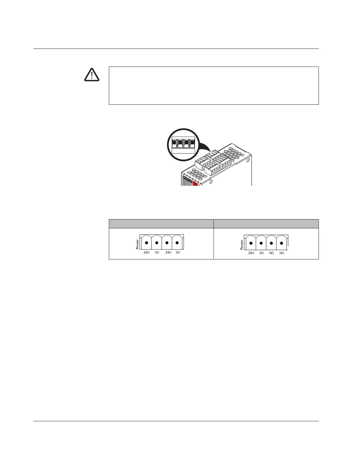
4.3.6 Connecting the supply voltage
The supply voltage is connected via a plug-in screw terminal block, which is located on the
top of the device.
Figure 4-7 Connecting the supply voltage (TC MGUARD RS4000 4G)
The TC MGUARD RS4000 4G has a redundant supply voltage. If you only connect one
supply voltage, you will get an error message.
• Remove the plug-in screw terminal blocks for the power supply and the service con-
tacts.
• Wire the supply voltage lines of the X4 mGuard screw terminal block. Tighten the
screws on the screw terminal blocks with 0.5 ... 0.8 Nm.
• Insert the plug-in screw terminal blocks into the intended sockets on the top of the de-
vice.
Status LED P1 lights up green when the supply voltage has been connected properly. On
the TC MGUARD RS4000 4G, the status indicator P2 also lights up if there is a redundant
supply voltage connection.
The device boots the firmware. The Stat LED flashes green. The device is ready for opera-
tion as soon as the Ethernet socket LEDs light up. Additionally, the P1/P2 LEDs light up
green and Stat LED flashes green at heartbeat.
Redundant voltage supply (TC MGUARD RS4000 4G)
A redundant supply voltage can be connected. Both inputs are isolated. The load is not dis-
tributed. With a redundant supply, the power supply unit with the higher output voltage sup-
plies the TC MGUARD RS4000 4G alone. The supply voltage is electrically isolated from
the housing.
WARNING: The device is designed for operation with a DC voltage of
11 V DC ... 36 V DC/SELV, 800 mA maximum.
Therefore, only SELV circuits with voltage limitations according to
IEC 60950/EN 60950/VDE 0805 may be connected to the supply connections and the
signal contact.
Table 4-3 Supply voltage TC MGUARD RS4000/RS2000 4G
TC MGUARD RS4000 4G TC MGUARD RS2000 4G
 Loading...