44 PianoDisc Installation Guide
228CFX - PianoCD - iQ
Step 22: Locating the access hole in the rail
cover and mounting the CPU
Note: CPU is mounted outside of the rail cover.
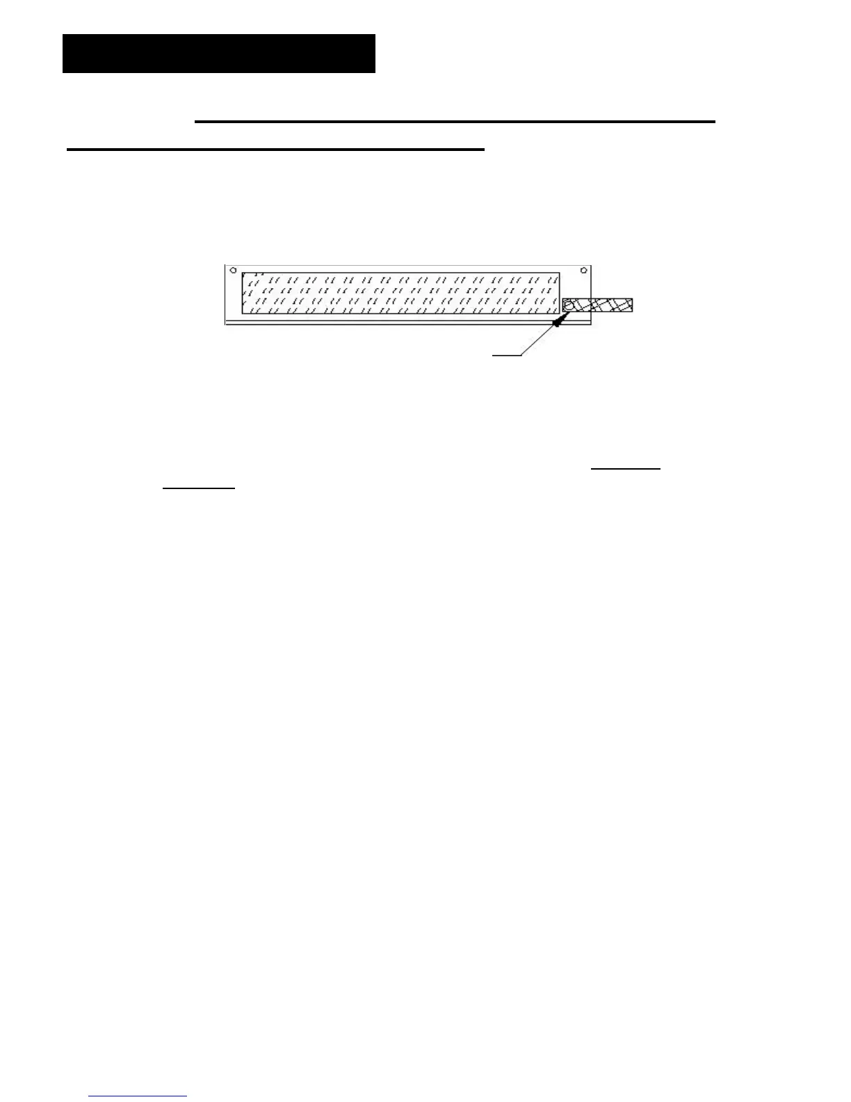
A. Attach a 8” ground strap to the ground post on the CPU (See Figure 27)
Driver CPU
Figure 27
A. Place the CPU on the keybed at the location marked in step 13 and center
the CPU to the opening. The sheet metal of the CPU must line up with the
line from the rail cover. Note: The CPU remains mounted, DO NOT
REMOVE.
B. Mount the rail cover on the keybed in the location outlined.
C. Place the sustain and the sostenuto trapwork back on the piano. Next,
place the lyre on the piano.
D. Looking through the drilled pitman holes of the 2 levers, place a mark on the
rail cover. These will be punched out to allow access for the threaded rod to
pass through.
E. Mark the rail cover for the two-screw locations for securing the CPU to the
rail cover.
F. Remove the trapwork and rail cover.
G. Drill two 3/8” (9.5 mm) holes through the rail cover for the threaded rod and
use a 1” Greenlee hole punch (part # 20670) to finish the hold cut.
H. Use a size 47 (.078) or (2.0 mm) drill bit for the CPU to rail cover
connections. Clean off the burrs inside with a file.
Attach ESD strap to ground stud here