User’s Manual of IMG-2x00T Modbus Gateway Series
2.1.5 Wiring the Power Inputs
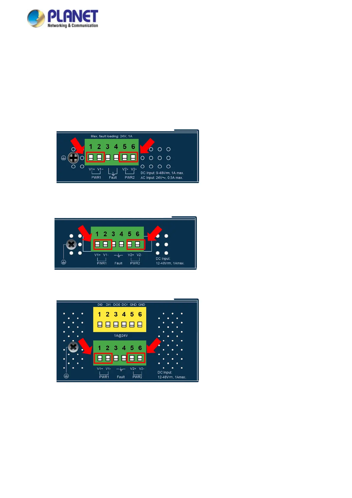
The upper panel of the Modbus Gateways indicates a DC inlet power socket and consists of one terminal block connector within
6 contacts. Please follow the steps below to insert the power wire.
1. Insert positive/negative DC power wires into Contacts 1 and 2 for Power 1, or Contacts 5 and 6 for Power 2. Figure 2-1-3
to 2-1-5 show PWR1 and PWR2 of the Modbus Gateways
IMG-2100T/IMG-2105AT/IMG-2102T/IMG-2102TS: 9~48V DC or 24V AC
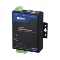
Figure 2-1-3 IMG-2100T/IMG-2105AT/IMG-2102T/IMG-2102TS Upper Panel
IMG-2200T: 12~48V DC
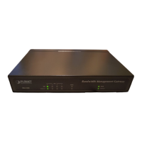
Figure 2-1-4 IMG-2200T Upper Panel
IMG-2400T: 12~48V DC
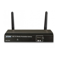
Figure 2-1-5 IMG-2400T Upper Panel
2. Tighten the wire-clamp screws for preventing the wires from loosening.
 Loading...