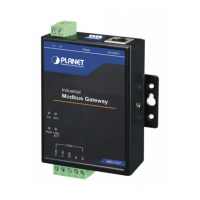
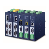
User’s Manual of IMG-2x00T Modbus Gateway Series
2.2 Installing the Modbus Gateway
This section describes how to install your Modbus Gateway and make connections to the Modbus Gateway. Please read the
following section and perform the procedure in the order being presented. To install your Modbus Gateway on a desktop or rack,
simply complete the following steps.
2.2.1 Installation Steps
1. Unpack the Modbus Gateway
2. Check if the DIN-rail bracket is screwed on the Modbus Gateway or not. If the DIN-rail bracket is not screwed on the
Modbus Gateway, please refer to DIN-rail Mounting section for DIN-rail installation. If users want to wall-mount the
Modbus Gateway, please refer to the Wall Mount Plate Mounting section for wall-mount plate installation.
3. To hang the Modbus Gateway on the DIN-rail track or wall.
4. Power on the Modbus Gateway. Please refer to the Wiring the Power Inputs section for knowing the information about
how to wire the power. The power LED on the Industrial Serial Server will light up. Please refer to the LED Indicators
section for indication of LED lights.
5. Prepare Network cables for Ethernet connection.
Use standard network (UTP) cables with RJ45
Use Multi-mode or Single-mode fiber patch cord with SC connector (IMG-2102T/IMG-2102TS only)
Use Multi-mode or Single-mode fiber patch cord with LC connector and 100BASE-FX SFP transceiver
(IMG-2105AT only).
6. Insert one side of RJ45 cable (category 5) or Fiber cable into the Modbus Gateway Ethernet port (RJ45/Fiber port)
while the other side to the network device’s Ethernet port (RJ45/SFP port), e.g., Switch PC or Server. The “LNK/ACT”
LED on the Modbus Gateway will light up when the cable is connected with the network device. Please refer to the LED
Indicators section for LED light indication.
Make sure that the connected network devices support MDI/MDI-X. If it does not support,
use the crossover Category 5 cable.
7. When all connections are set and all LED lights show normal, the installation is completed.
 Loading...