8 SYSTEM DESCRIPTION
14 Planmeca ProScanner User’s & installation manual
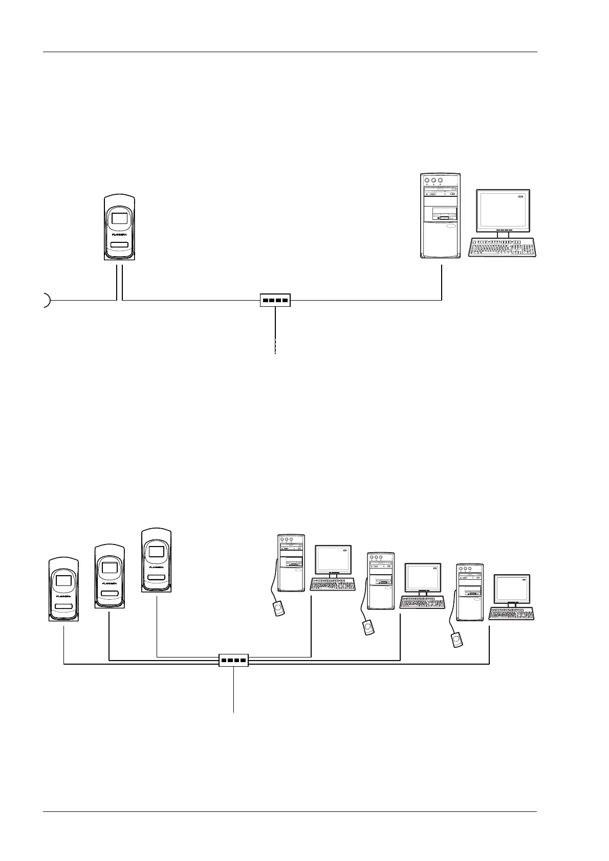
8.2 1-to-1 Ethernet network configuration
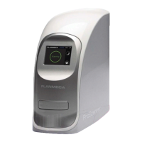
Planmeca ProScanner is attached to a HUB/
switch using Ethernet connection. Crossed or
straight Ethernet cable can be used depending
on the HUB/switch type.
8.3 N-to-N Ethernet
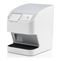
Planmeca ProScanner can be shared in the
network between several treatment rooms.
Planmeca ProScanner is attached to a HUB/
Switch using Ethernet connection. Planmeca
ProID readers are attached to the PC in the
treatment rooms with mini USB cable.
100 - 240 VAC
Romexis PC
Planmeca
ProScanner
Hub
Ethernet cable Max. 100m
CAT.5E, RJ45 FTP
Cross / Direct Type Cable
Ethernet cable Max. 100m
CAT.5E, RJ45 FTP
Cross / Direct Type Cable
Romexis PCPlanmeca
ProScanner
Hub
Ethernet cable Max. 100m
CAT.5E, RJ45 FTP
Cross / Direct Type Cable
Ethernet cable Max. 100m
CAT.5E, RJ45 FTP
Cross / Direct Type Cable