Pleiger Elektronik
GmbH & Co. KG
Page: 46 Manual for 362MC Edition: 6/2007 Subject to modifications
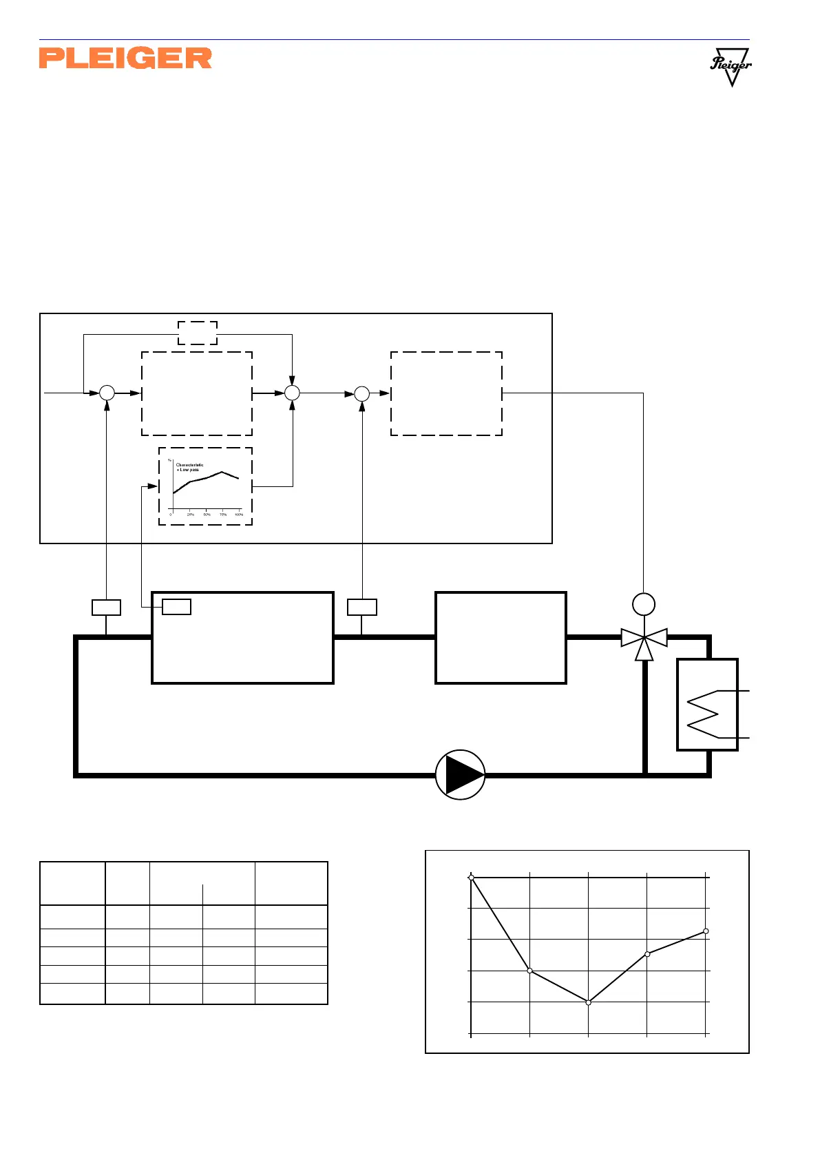
A possible characteristic for this application:
(arbitrary values used for purpose of illustration)
The values for Setp V apply for Setp W=80.0°C,
Kw
2
=1 and Setp W=ActV X (Y=0 compensated).
Kz TS Value Z Setp V
mA % °C °C
0% 4 0.0 0.0 80.0
25% 8 - 6.0 -12.0 68.0
50% 12 - 8.0 -16.0 64.0
75% 16 - 5.0 -10.0 70.0
100% 20 - 3.5 - 7.0 73.0
disturbance value
0 % 25 % 50 % 75 % 100 %
0 % 0°C
- 2 % - 4°C
- 4 % - 8°C
- 6 % - 12°C
- 8 % - 16°C
- 10 % - 20°C
Weighting (added to controller output)
Weighting (added to setpoint)
Graph of the characteristic:
Example
The following circuit diagram shows a typical example of use of the special disturbance compensation
function. The outlet temperature (T
OUT
) of a main engine is controlled using a cascade step controller
(CtrlTyp=CscStep), whereby the secondary control circuit reduces the turbo-charger´s disturbing effects
on the inlet temperature (T
IN
). By means of the special disturbance compensation function (parameter
Disturb = Lin 4..), a measured value for engine output (TS) is weighted via the characteristic and
delayed by means of the low pass and then added to controller output Y of the primary controller. In this
way, the setpoint for the inlet temperature is adjusted before the disturbance is able to manifest itself in
the form of an altered outlet temperature.
Setp W
-
Y Setp V
+-
Cooler
M
PT100-2
ActV U
Out+Y
1Relay
Continuous
PID controller
primary
PT100-1
ActV X
3-Point
step controller
secondary
Main engine
T
OUT
PT100
T
IN
PT100
TT
TT
Turbo charger
engine output value
(4-20 mA)
TS
Lin 4..
Dist Z
+
Z
362MC
Kw
2