FINAL DRIVE
7.23
16--19 ft.lbs.
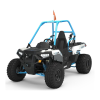
NOTE:The chainmaybeinstalledat this point or later
in the procedure.
3. Install the spacer and sprocket guard (D). Install
the sprocket guard nuts, torque to 25--30 ft.lbs.
(34--41 Nm).
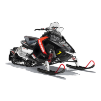
4. Install theO--ring (E),brakedisc (F), and axle nut
(G) onto the axle.
G
F
E
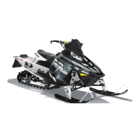
5. Install the retaining ring (H) onto the axle. It
should fully seat into the groove.
6. Turn the axle nut outward with a 1 3/4” Wrench
(PN 2870772)untiltheend oftheaxlenut (G)just
covers the retaining ring (H). The retaining ring
should still be visible under the axle nut from an
angle. Torque to 8--10 ft.lbs. (11--14 Nm)
H
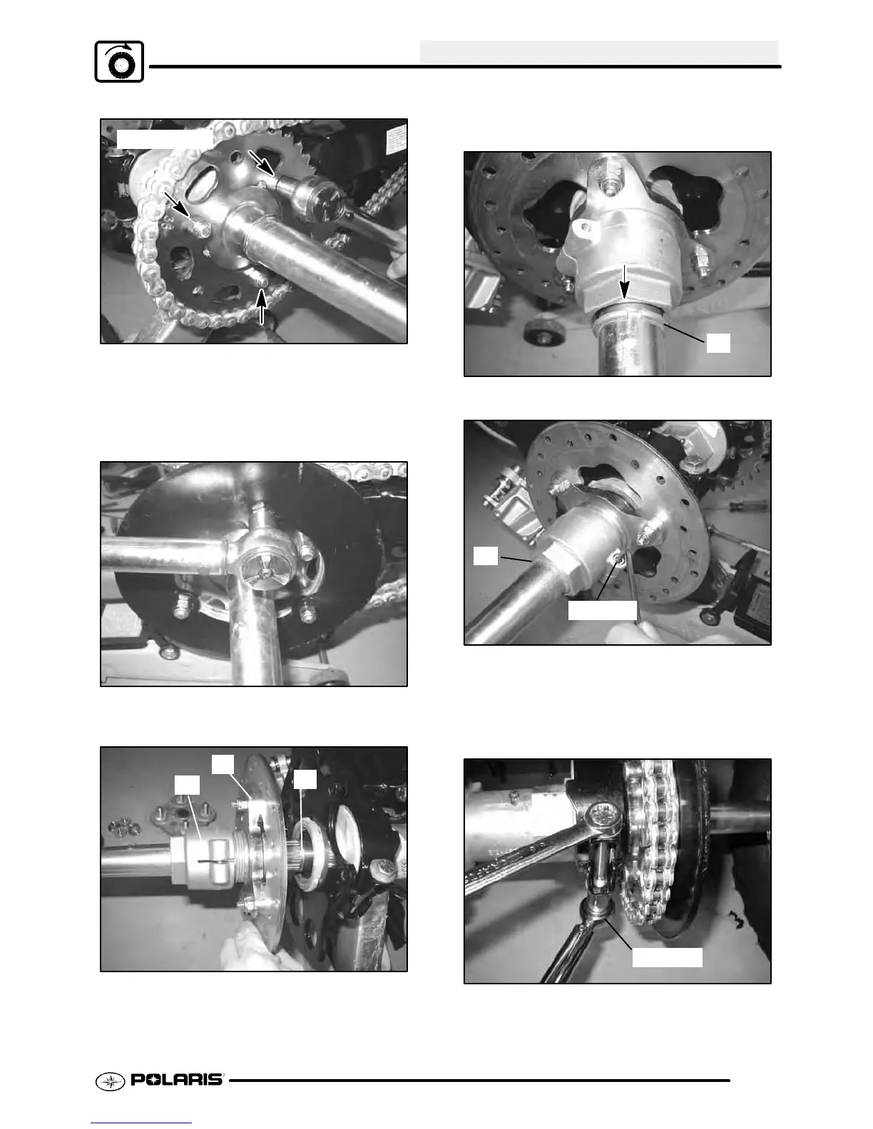
7. Torque theaxle nut pinch bolt to 50in.lbs. (6Nm).
50 in.lbs.
H
8. Reinstall the chain and master link. To verify
proper chain tension, refer to Chapter 2 “DRIVE
CHAIN INSPECTION” for this procedure.
9. Torque the eccentric clamp bolts to 35 ft.lbs. (47
Nm).
35 ft.lbs.
10. Installcaliper,twomountingboltsand lockwashers.
Torque mounting bolts to 18 ft.lbs. (25 Nm).

 Loading...