ELECTRICAL
10.6
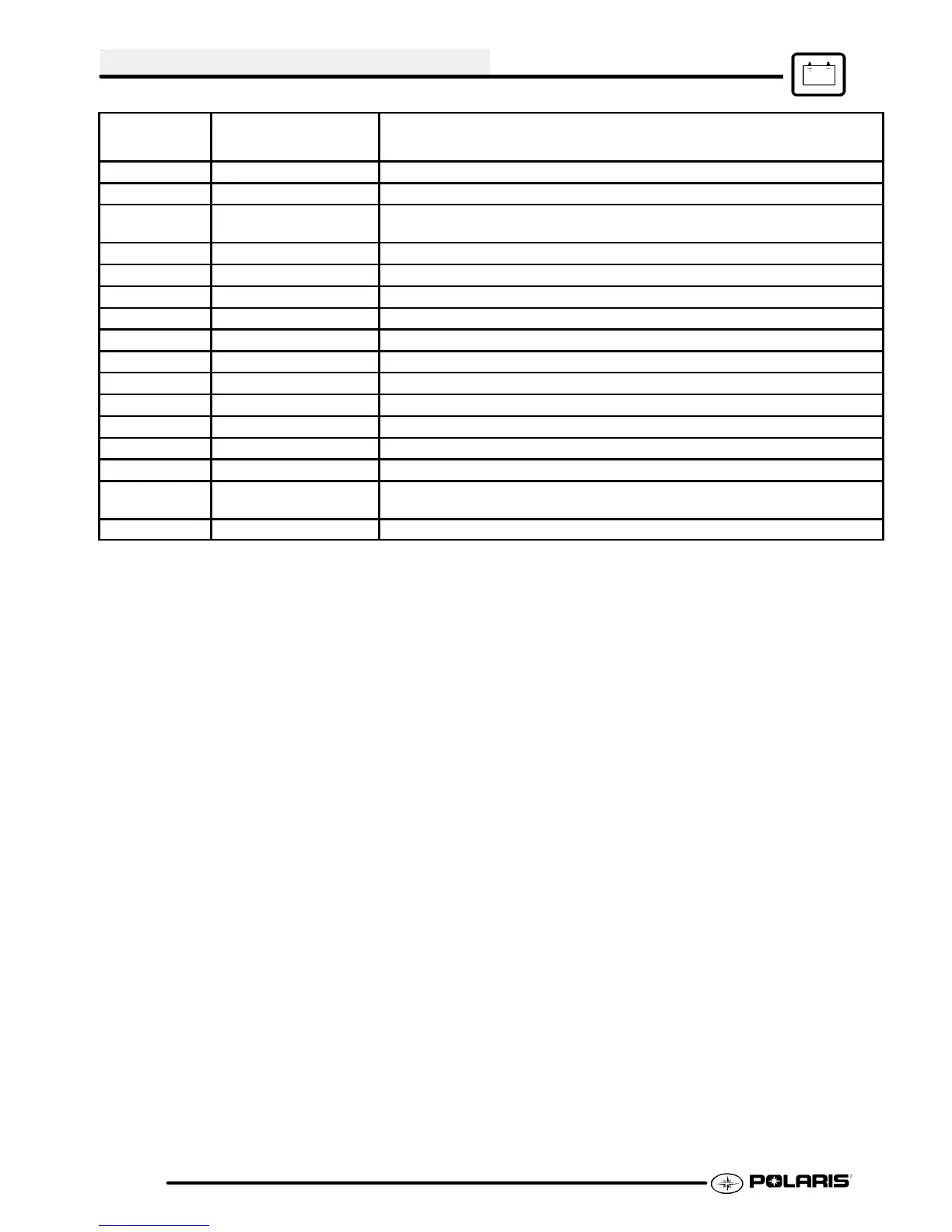
Connector 1
Pin #
Signal Name Description
IPS = Intelligent Power Switch
J1--A STARTER Starter output provides ground path when active.
J1--B BRAKE Brake input for starter lockout. Active high.
J1--C RUN PDM enable input. Connected to BAT_PROT via ignition and run
switches.
J1--D HOT_INDICATOR Engine hot signal. Provides a ground path for the hot indicator lamp
J1--E THERM_RTN Thermistor ground
J1--F THERM Thermistor input
J1--G TRANS Transmission signal voltage input for starter lockout
J1--H LIGHTS Powers vehicle lighting
J1--J COIL 3 Alternator coil input
J1--K COIL 2 Alternator coil input
J1--L COIL 1 Alternator coil input w/resistance to ground
J1--M BAT+ Battery Positive
J1--N ACC_PWR IPS that provides power to the accessories
J1--P GND Battery Ground
J1--R BAT_PROT SSCB output provides battery power to loads. Also provides constant
power for real time clock.
J1--S FAN Relay control input to enable operation of the fan

 Loading...