ELECTRICAL
10.15
CRANKING OUTPUT TEST
WITH PEAK
READING
VOL
TMETER
The following peak voltage tests will measure the
amount of output directly from each component.
A
peak readingvoltmeter shouldbe usedtoperform
the
CDI output test
. A variety of peak reading adaptors
arecommerciallyavailableforusewiththeFluke t77
DigitalMultimeter(PV--43568)andotherdigitalVOMs
which will allow peak voltage tests to be performed
accurately. Follow the directions provided with the
adaptor. All measurementsare indicatedin DCVolts.
Readingsobtainedwithoutapeakreadingadaptorwill
be significantly different.
The startersystem must be in good condition, engine
undamaged and the battery fully charged.
240 Watt 4 Stroke (500)
Test Connect
Meter Wires
To:
Reading
(Without P eak
Reading Volt
meter)
Cranking
Voltage
Red on CDI
connector and
ground
6--9 DCV
CDI OUTPUT TEST USING
PEAK READING ADAPT
OR
Re-connect all CDI wires. Disconnect CDI module
wire from ignition coil primary terminal. Connect one
meter lead to engine ground and the other to the
ignitioncoilprimarywireleadingfromtheCDImodule.
Crank engine and check output of CDI wire to coil.
Reconnect coil wire to CDI when finished.
Average Output w/ Peak output tester
130 DCV
Average Output w/ Digital Voltmeter
20 DCV
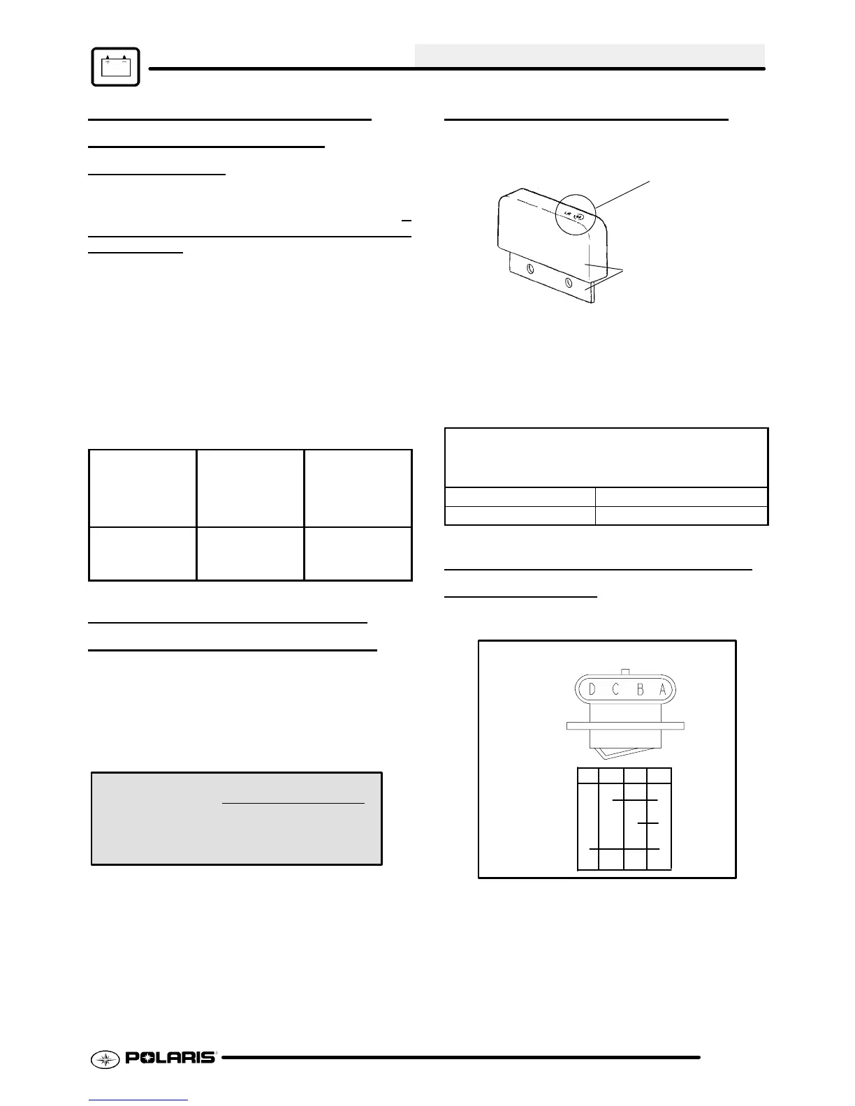
LIMITER SPECIFICATIONS
Speed Limiter
Module LR
ID Number
Part number is printed
on module
NOTE:Thepart number isprintedonsomelatemodel
LR modules. W he never possible, us e tha t pa rt number
to identify the module. Modules may have same “LR”
I.D. number , but may have different part numbers,
terminals, and internal functions.
LIMITER SPECIFICATIONS
Refer to parts manual or microfiche
for part number and application.
FUNCTION / LIMIT RPM COMMENTS
Reverse Limit - 3100 Scrambler 500
GEAR POSITION INDICATOR
SWITCH
TEST
Switch Continuity Table/Switch Schematic
High Range
Neutral
Reverse
F
F
F
F
DCBA
F
F
High/Neutral/Reverse Switch

 Loading...