ENGINE
3.30
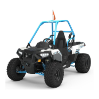
PISTON-TO-CYLINDER
CLEARANCE
40 mm
Piston
Piston Pin
1. Measurepistonoutsidediameteratapoint40mm
down from the top of the piston at a right angle to
the direction of the piston pin.
2. Subtract this measurement from the maximum
cylinder measurement obtained in Step 5 above.
Piston to Cylinder Clearance
Std: .0006-.0018I (.015- .045 mm)
Piston O.D.:
Std: 3.6204-3.6215I (91.970-91.985 mm)
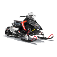
PISTON/ROD INSPECTION
Piston Pin Bore
Piston Pin Bore:
.9055-.9057I (23.0- 23.006 mm)
1. Measure piston pin bore.
Piston Pin Measurement Locations
Piston Pin O.D.
.9053-.9055I (22.994- 23.0 mm)
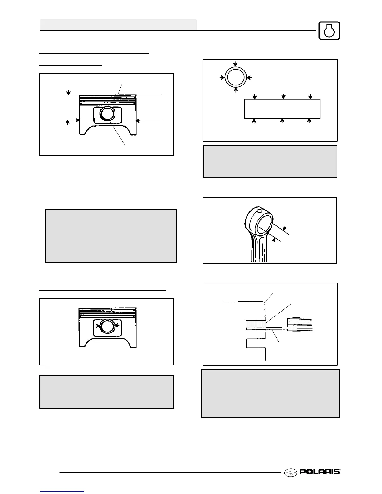
2. Measure piston pin O.D. Replace piston and/or
piston pin if out of tolerance.
3. Measure connecting rod small end ID.
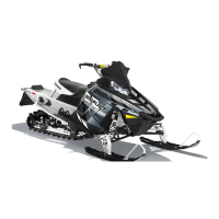
Piston
Ring
Feeler Gauge
Piston Ring-to- Groove Clearance
Top Ring Std: .0016-.0031I (.040-.080 mm)
Limit: .0059I (15 mm)
Second Ring Std: .0012-.0028I (.030-.070 mm)
Limit: .0059I (15 mm)
4. Measure piston ring to groove clearance by
placing the ring in the ring land and measuring
with athickness gauge. Replacepistonandrings
if ring-to-groove clearance exceeds service
limits.

 Loading...