3-4
3 First Steps
3.3 Control Elements, Displays and Connections
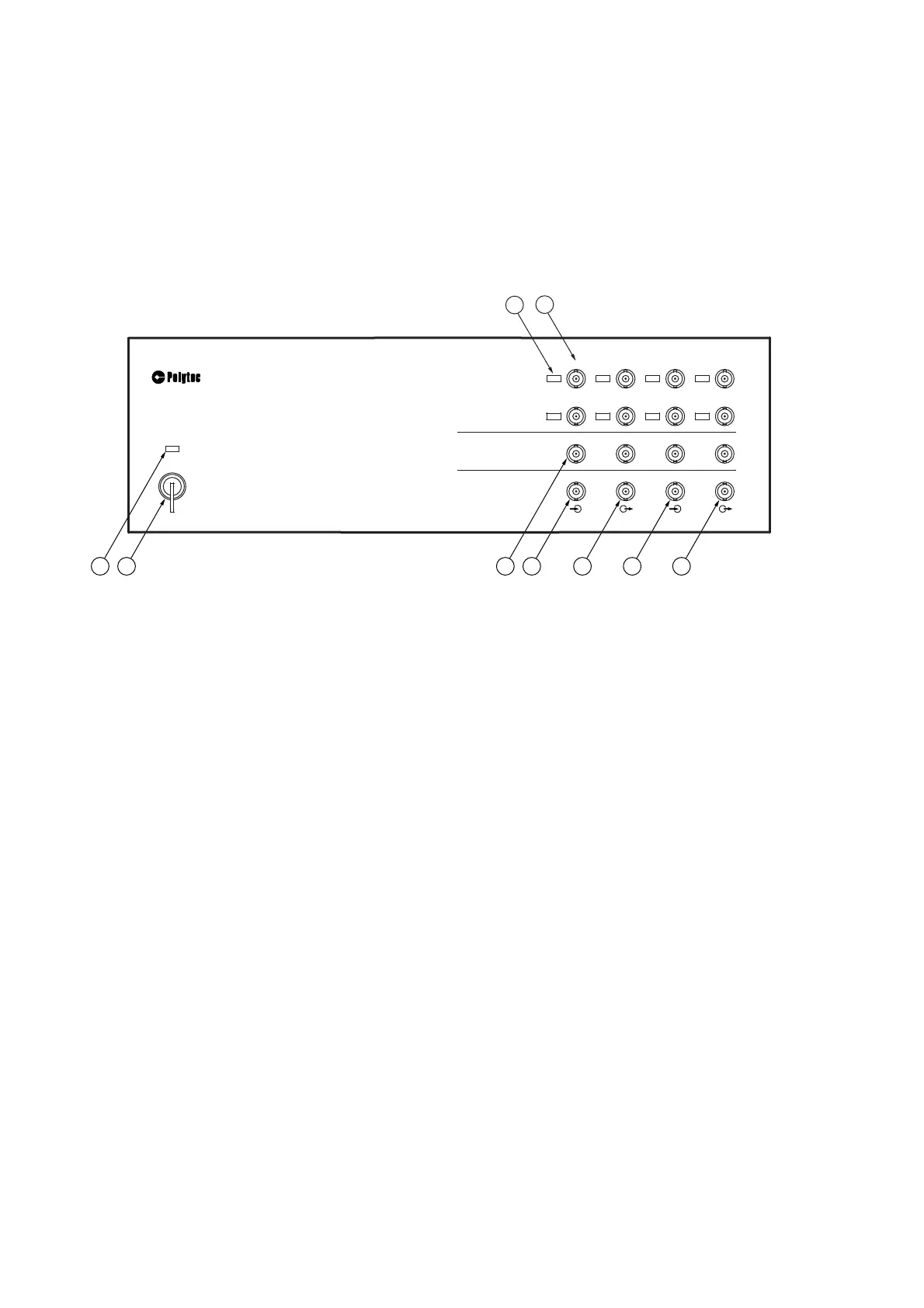
3.3.1 PSV-F-500-HM Front-End
Front view
The connections on the front are only used for the operation as an H system
(exception: AUX IN and AUX OUT). The front view of the front-end is shown in
the following figure.
Figure 3.1: Front view of the front-end
1IEPE1
to
IEPE 8
L
ED
s
L
ED
is lit up: IEPE power supply for the corresponding reference input (REF 1 to
REF 8) activated in the software
2REF1
analog input (BNC jack)
Analog voltage input for the reference signal. You can also connect a sensor
equipped with an integrated amplifier to this input, according to the IEPE concept,
also known as ICP® (4 mA/24V). Activating or deactivating the IEPE power
supply is described in your software manual.
REF 2
to
REF 8
analog inputs (BNC jacks)
There are up to seven additional analog voltage inputs are available for reference
signals.
3SYNC
TTL output (BNC jack)
TTL output for the SYNC signal of the function generator
4TRIGIN
TTL input (BNC jack)
TTL input for an external trigger signal
5AUXOUT
TTL output (BNC jack)
TTL output for special applications (programmable via Visual Basic® Engine)
6AUXIN
TTL input (BNC jack)
TTL input for special applications and also to connect the PSV-A-430 acoustic
gate unit (programmable via Visual Basic® Engine)
9 8
6
5 4
3
7
1
2
IEPE
IEPE
IEPE
IEPE
IEPE
IEPE
IEPE
PSV-500
VIBROMETER FRONT-END
O
I
POWER
ANALOG IN
GENERATOR OUT
DIGITAL I/O
AUX IN
TRIG IN
AUX OUT
SYNC
SIGNAL1
SIGNAL2
SIGNAL3
SIGNAL4
REF5 REF6
REF8
REF7
REF1
REF2
REF3
REF4
IEPE