3-6
3 First Steps
3.3.2 PSV-E-530 Junction Box
The PSV-E-530 junction box is only used for the operation as an M system.
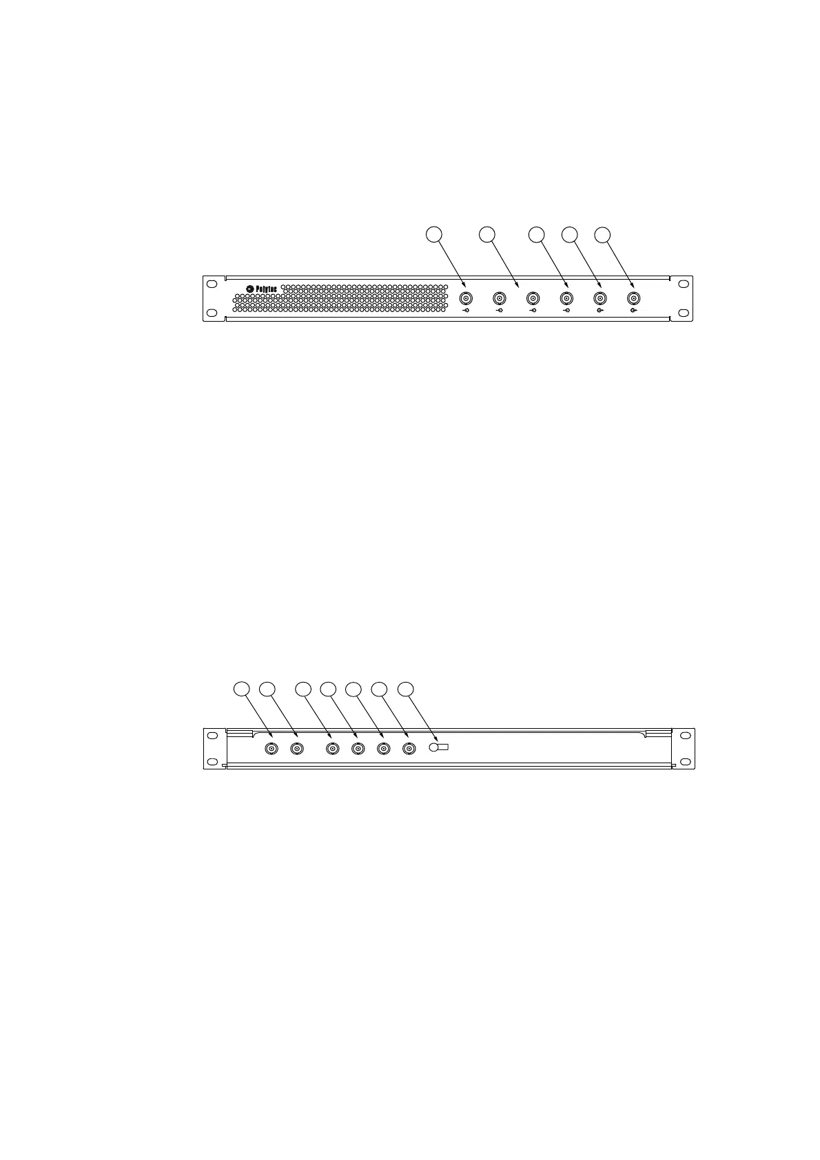
Front view
The front view of the junction box is shown in the following figure.
Figure 3.3: Front view of the junction box
1REF1
analog input (BNC jack)
Analog voltage input for the reference signal
2REF2
to
REF 3
analog inputs (BNC jacks)
There are up to two additional analog voltage inputs available for reference
signals (not for PSV-3D).
3TRIGIN
TTL input (BNC jack)
TTL input for an external trigger signal
4SYNC
TTL output (BNC jack)
TTL output for the SYNC signal of the function generator
5SIGNAL
generator output (BNC jack)
Analog voltage output for the signal of the function generator
Back view
The back view of the junction box is shown in the following figure.
Figure 3.4: Back view of the junction box
1Ch0
signal input (BNC jack)
Connection for the BNC-SMB connecting cable (Ch0) from the PC
2D0
signal input (BNC jack)
Connection for the BNC-SMB connecting cable (D0) from the PC
3TRIG
signal output (BNC jack)
Connection for the TRIG line of the ACQ HM acquisition cable from the PC
4REF3
signal output (BNC jack)
Connection for the AI_3 line of the ACQ HM acquisition cable from the PC
5REF2
signal output (BNC jack)
Connection for the AI_2 line of the ACQ HM acquisition cable from the PC
REF 1
REF 2
REF 3
TRIG IN
SYNC
SIGNAL
12
3 4
5
Ch0
D0
TRIG
REF 3
REF 2
REF 1
12
3 4
56
7