3-12
3 First Steps
Back view
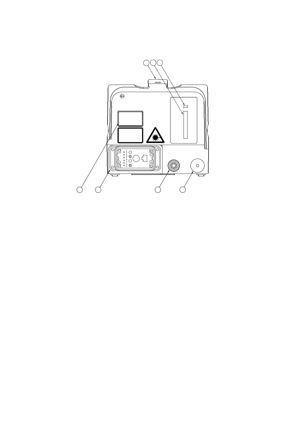
The back view of the scanning head is shown in the following figure.
Figure 3.9: Back view of the scanning head
1
Transport handle
2SIGNAL
level display
Measure for the light scattered back form the measurement surface The signal
level display is deactivated when the geometry laser (Geo-Laser) is activated.
3 LASER
L
ED
L
ED
is lit up: scanning head cabled correctly, laser switched on
4 10-32 UNF-2B
thread
Connection for a compensation sensor
5OPTION
connection (7-pin circular jack)
Connection for the connecting cable to the PSV-A-T11 pan-tilt head to control the
pan-tilt head via the software (not for PSV-3D).
With option EXT:
OPTION
connection (8-pin circular jack)
Connection for the connecting cable to the external scanner control
6
Main connection (industrial-style connector)
Connection for the main cable (Umbilical) to the front-end/ to the junction box
7
Identification label
On the identification label you will find, among other things, the serial number of
the instrument.
PSV-500
SCANNING HEAD
Polytec
LASER
SIGNAL
OPTION
10-32
UNF-2B
2
3
5
1
4
6
7