9
PORA ELECTRIC MACHINERY CO.,LTD.
PR-DTC-4100.A / AD
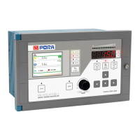
5) Digital input
Circuit for digital input is as the below. When using digital contact point, please make the volume of external
contact point right.
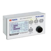
6) Digital output
Circuit for digital output is as the below. When using digital output contact point, please be sure not to overload
more than contact point volume.
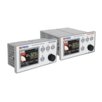
7) Analog input
Analog input circuit is as below. Please be sure to check if the way of input which you hope to use at analog
input selection in setting menu is Voltage (0~10V) or Current (4~20mA).
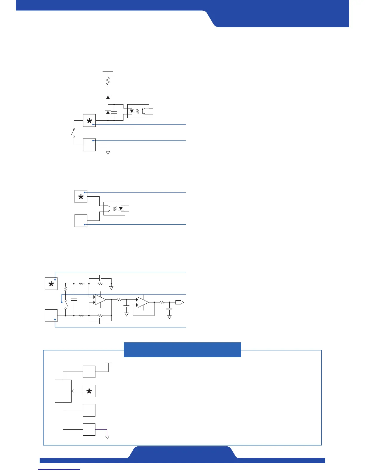
When connecting potentiometer
In case of using by connecting potentiometer outside, please
arrange circuit as the below.
Please connect signal line of potentiometer to Al+ terminal
and Al- terminal to No.20 terminal (GND).
Please set the analog input at analog input section in setting
menu to be voltage (0~10V)
#
5V
5K
19
20
24V
7
Terminal block
*
shows each terminal number of
No. 1~6.
Terminal 7 is a common line of digital contact point
output.
#
+
-
+
-
249Ω
SW
Terminal
*
shows Al+ (No. 21,23,25) block.
Terminal # shows Al- (No.22,24,26) block.
Internal SW runs according to the choice of
voltage or current. Please set accordingly to
the way of analog input signal.
 Loading...